
Page 544 - Dynamics of Mechanical Systems
P. 544
0593_C15_fm Page 525 Tuesday, May 7, 2002 7:05 AM
Balancing 525
15.6 Lanchester Balancing Mechanism
With the primary unbalancing force somewhat counteracted we may direct our attention
to balancing the smaller secondary unbalancing force. This may be accomplished by a
mechanism that develops an equal but opposite inertia force to that of the secondary
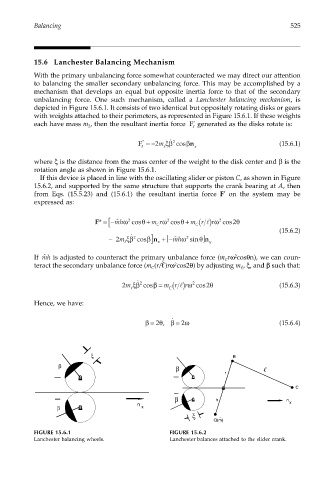
unbalancing force. One such mechanism, called a Lanchester balancing mechanism, is
depicted in Figure 15.6.1. It consists of two identical but oppositely rotating disks or gears
with weights attached to their perimeters, as represented in Figure 15.6.1. If these weights
each have mass m , then the resultant inertia force F * generated as the disks rotate is:
2 l
F =−2m ξβ ˙ 2 cosβ n (15.6.1)
*
l l x
where ξ is the distance from the mass center of the weight to the disk center and β is the
rotation angle as shown in Figure 15.6.1.
If this device is placed in line with the oscillating slider or piston C, as shown in Figure
15.6.2, and supported by the same structure that supports the crank bearing at A, then
*
from Eqs. (15.5.23) and (15.6.1) the resultant inertia force F on the system may be
expressed as:
[
F* =−mhω 2 cos + m rω 2 cos + m r 2 cos θ
θ
θ
ˆ
( )rωl
2
C
C
− m ξβ ˙ 2 cosβ n ] x +− [ ˆ mhω 2 sin n ] θ y (15.6.2)
2
l
If ˆ mh is adjusted to counteract the primary unbalance force (m rω cosθn), we can coun-
2
C
2
teract the secondary unbalance force (m (r/ )rω cos2θ) by adjusting m , ξ, and β such that:
C
C(
2 ˙
β
2m ξβ cos = m r l) rω cos 2θ (15.6.3)
2
l
Hence, we have:
˙
β = 2 θ, β = 2 ω (15.6.4)
ξ B
β β
r
C
β h n
n x
β x
ξ
ˆ
Q(m)
FIGURE 15.6.1 FIGURE 15.6.2
Lanchester balancing wheels. Lanchester balances attached to the slider crank.