Page 539 - Dynamics of Mechanical Systems
P. 539

0593_C15_fm  Page 520  Tuesday, May 7, 2002  7:05 AM


                       520                                                 Dynamics of Mechanical Systems


                       Solving these equations for x, y, and z we obtain:

                                                                       /
                                                             B
                                                                     B
                                                        x ˆ  I I B  2 mI ] 12
                                                    x =− =[ 23 12
                                                                     13
                                                                       /
                                                                     B
                                                        y ˆ  B  B  mI ] 12
                                                            I I
                                                    y =− =[ 12 13  2                          (15.4.17)
                                                                     23
                                                                       /
                                                        z ˆ  I I  B  2 mI ] 12
                                                                    B
                                                             B
                                                    z =− =[ 13 23
                                                                    12
                        These results show that if the products of inertia are relatively small, B can be balanced
                                                                        ˆ
                                                                       P
                       dynamically by placing small weights at points P and   at opposite ends of a line whose
                       midpoint is at the mass center of B. The resulting inertia dyadic components are then:
                                              m y + )
                                         I + (  2  z  2        0               0      
                                          B
                                             2
                                          11
                                                                (
                                     B ˆ
                                    I =      0         I + 2 m x + )          0           (15.4.18)
                                                                  2
                                                                     2
                                                          B
                                                                    z
                                     ij                   22
                                                                               m x + )
                                                                         I + (   2   2  
                                                                           B
                                              0                0          33  2     y  
                       Hence, the axes X, Y, and Z become principal inertia axes; thus, the weighted body is
                       stable in rotation about each of these axes.
                       15.5 Application: Balancing of Reciprocating Machines
                       We can further illustrate the application of the foregoing ideas in the balancing of recip-
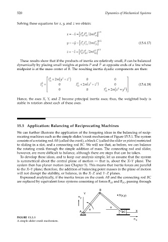
                       rocating machines such as the simple slider/crank mechanism of Figure 15.5.1. The system
                       consists of a rotating rod AB (called the crank), a block C (called the slider or piston) restricted
                       to sliding in a slot, and a connecting rod BC. We will see that, as before, we can balance
                       the rotating crank through the simple addition of mass. The connecting rod and slider,
                       however, are more difficult to balance, although there are steps that can be taken.
                        To develop these ideas, and to keep our analysis simple, let us assume that the system
                       is symmetrical about the central plane of motion  — that is, about the  X–Y plane. The
                       system then has planar motion (see Chapter 5). This means that inertia forces are parallel
                       to the X–Y plane; therefore, the addition of balancing point masses in the plane of motion
                       will not disrupt the stability, or balance, in the X–Z and Y–Z planes.
                        Expressed analytically, if the inertia forces on the crank AB and the connecting rod BC
                       are replaced by equivalent force systems consisting of forces F  and F , passing through
                                                                              AB     BC
                                                                       B
                                                              Y
                                                           n                       P(x,y)
                                                            y

                                                                              φ
                                                                 θ
                                                           A                          C      X
                       FIGURE 15.5.1                                                        n
                       A simple slider crank mechanism.                                      x
   534   535   536   537   538   539   540   541   542   543   544