Page 534 - Dynamics of Mechanical Systems
P. 534

0593_C15_fm  Page 515  Tuesday, May 7, 2002  7:05 AM


                       Balancing                                                                   515


                                                                                   n
                                                                                    2
                                                                           P  (m)
                                                                            1
                          A                       B                                               n  1
                                P
                                 1
                                                                                 G
                                                       ê
                                                                                        P  (m)
                                      G                                                  2
                                            P                             n
                                             2                             3
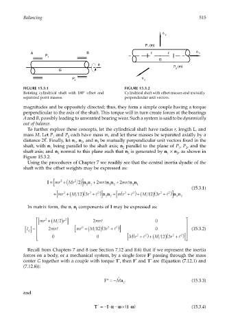
                       FIGURE 15.3.1                              FIGURE 15.3.2
                       Rotating cylindrical shaft with 180° offset and  Cylindrical shaft with offset masses and mutually
                       separated point masses.                    perpendicular unit vectors.
                       magnitudes and be oppositely directed; thus, they form a simple couple having a torque
                       perpendicular to the axis of the shaft. This torque will in turn create forces at the bearings
                       A and B, possibly leading to unwanted bearing wear. Such a system is said to be dynamically
                       out of balance.
                        To further explore these concepts, let the cylindrical shaft have radius r, length L, and
                       mass M. Let P  and P  each have mass m, and let these masses be separated axially by a
                                          2
                                   1
                       distance 2 . Finally, let n , n , and n  be mutually perpendicular unit vectors fixed in the
                                                       3
                                             1
                                                2
                       shaft, with n  being parallel to the shaft axis; n  parallel to the plane of P , P , and the
                                  1
                                                                  2
                                                                                          1
                                                                                             2
                       shaft axis; and n  normal to this plane such that n  is generated by n  × n , as shown in
                                                                                         2
                                                                                     1
                                      3
                                                                    3
                       Figure 15.3.2.
                        Using the procedures of Chapter 7 we readily see that the central inertia dyadic of the
                       shaft with the offset weights may be expressed as:
                                             2
                                                 n n + mrl
                                                                2
                                 I =[ mr 2  +(Mr 2 )] 11  2  n n + mrl n n 1                   (15.3.1)
                                                              2
                                                                      2
                                                            1
                                                                               (
                                                 (
                                                                                      2
                                                       2
                                                                      2
                                                                     l
                                                                                     l
                                                               [ m
                                                      l
                                    +[ mr  2  +(M 12 ) r3  2  + ) ] nn + (r  2  + ) +(M 12 ) r3  2  + ) ] nn 3
                                                            2
                                                          2
                                                                                         3
                        In matrix form, the n  n components of I may be expressed as:
                                              j
                                           i
                             [ mr +( M ) ]          2 mrl                      0            
                                2
                                         2
                                        r
                                      2
                                                         (
                         ij []
                        I =    2 mrl        m [ l 2  +  M (  12 ) 3 r + ) ]   0                (15.3.2)
                                                           2
                                                               2
                                                              l
                                                                   [  (             (       
                                                                           2
                                                                        2
                                                                                       2
                                                                                           2
                                                                                  12
                                                                           l
                                                                                          l
                                 0                  0             Mr + ) +(  M ) 3  r + ) ] 
                        Recall from Chapters 7 and 8 (see Section 7.12 and 8.6) that if we represent the inertia
                       forces on a body, or a mechanical system, by a single force F  passing through the mass
                                                                             *
                                                                       *
                       center G together with a couple with torque T , then F  and T  are (Equation (7.12.1) and
                                                                *
                                                                              *
                       (7.12.8)):
                                                                ˆ
                                                          F* =−M a                             (15.3.3)
                                                                  G
                       and
                                                            α
                                                     T =− ⋅ −αωω × ⋅ (ΙΙωω )                   (15.3.4)
                                                           I
                                                       *
   529   530   531   532   533   534   535   536   537   538   539