
Page 533 - Dynamics of Mechanical Systems
P. 533
0593_C15_fm Page 514 Tuesday, May 7, 2002 7:05 AM
514 Dynamics of Mechanical Systems
δ
D
S O
G
A A
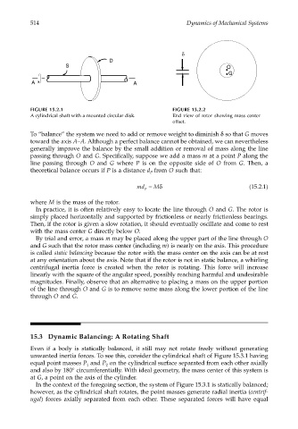
FIGURE 15.2.1 FIGURE 15.2.2
A cylindrical shaft with a mounted circular disk. End view of rotor showing mass center
offset.
To “balance” the system we need to add or remove weight to diminish δ so that G moves
toward the axis A–A. Although a perfect balance cannot be obtained, we can nevertheless
generally improve the balance by the small addition or removal of mass along the line
passing through O and G. Specifically, suppose we add a mass m at a point P along the
line passing through O and G where P is on the opposite side of O from G. Then, a
theoretical balance occurs if P is a distance d from O such that:
P
md = Mδ (15.2.1)
P
where M is the mass of the rotor.
In practice, it is often relatively easy to locate the line through O and G. The rotor is
simply placed horizontally and supported by frictionless or nearly frictionless bearings.
Then, if the rotor is given a slow rotation, it should eventually oscillate and come to rest
with the mass center G directly below O.
By trial and error, a mass m may be placed along the upper part of the line through O
and G such that the rotor mass center (including m) is nearly on the axis. This procedure
is called static balancing because the rotor with the mass center on the axis can be at rest
at any orientation about the axis. Note that if the rotor is not in static balance, a whirling
centrifugal inertia force is created when the rotor is rotating. This force will increase
linearly with the square of the angular speed, possibly reaching harmful and undesirable
magnitudes. Finally, observe that an alternative to placing a mass on the upper portion
of the line through O and G is to remove some mass along the lower portion of the line
through O and G.
15.3 Dynamic Balancing: A Rotating Shaft
Even if a body is statically balanced, it still may not rotate freely without generating
unwanted inertia forces. To see this, consider the cylindrical shaft of Figure 15.3.1 having
equal point masses P and P on the cylindrical surface separated from each other axially
1
2
and also by 180° circumferentially. With ideal geometry, the mass center of this system is
at G, a point on the axis of the cylinder.
In the context of the foregoing section, the system of Figure 15.3.1 is statically balanced;
however, as the cylindrical shaft rotates, the point masses generate radial inertia (centrif-
ugal) forces axially separated from each other. These separated forces will have equal