
Page 545 - Dynamics of Mechanical Systems
P. 545
0593_C15_fm Page 526 Tuesday, May 7, 2002 7:05 AM
526 Dynamics of Mechanical Systems
and
m ξ= m r 8 l (15.6.5)
2
l C
That is, the Lanchester gears are driven at twice the angular speed as the rotating crank.
15.7 Balancing of Multicylinder Engines
We can further apply the concepts of balancing and the analysis of the foregoing sections
in the balance of multicylinder engines, such as automobile engines. To develop this
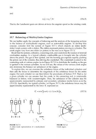
concept, consider first the system of Figure 15.7.1 which depicts an inline multi-
slider/crank system with n sliders. The sliders represent pistons moving in cylinders. The
crank angles vary from one slider (or piston) to the next as in Figure 15.7.2.
Recall that the pistons, cylinders, connecting rods, and crank form the essence of internal
combustion engines. In a typical cylinder, combustible gas is brought into the cylinder
above the piston. The gas is then ignited, and the burning gas expands rapidly, pushing
the piston out of the cylinder, thus driving the crankshaft. The crankshaft is joined to the
connecting rods at various angles (as in Figure 15.7.2) to distribute the loading as the gas
is ignited in the various cylinders. As we will see, the values of the various crank angles
also determine the balance (or unbalance) of the engine.
To explore this, we can examine the unbalance forces of the individual cylinders and
then add the forces to determine the magnitude of the unbalance forces for the entire
engine. For each cylinder we can then follow the procedures of Section 15.5. That is, for
a given cylinder we can assume that the crank, at the connecting rod, is rotationally
balanced as before, with counterweights. Then, the unbalance of the cylinder may be
approximately represented by primary and secondary unbalance inertia forces as in Eq.
(15.5.22). Specifically, for typical cylinder i of Figure 15.7.1, the unbalance forces may be
approximately represented by the force F * expressed as:
i
F = mrω 2 [ cosθ + r cos θ i] n (15.7.1)
*
2
i i ( ) l y
1 2 3 i n
n y
1
2 φ φ
φ
3
2
1
n
φ n
3
a a
n
x
n
z
FIGURE 15.7.1 FIGURE 15.7.2
A slider/crank representation of a multicylinder Crank angles.
engine.