Page 546 - Dynamics of Mechanical Systems
P. 546
0593_C15_fm Page 527 Tuesday, May 7, 2002 7:05 AM
Balancing 527
where as before m is the mass concentrated at the piston, r is the crank radius, is the
length of the connecting rod, ω is the angular speed of the crankshaft (assumed to be
constant), and θ is the angular position of the crank arm. In terms of the connecting rod
i
crank angles of Figure 15.7.2, θ may be expressed as:
i
θ φ
θ =+ (15.7.2)
i i
where θ is the crank rotation angle. In our analysis we will assume that the n piston/cyl-
inders are identical, with each having the same geometrical dimensions and each having
the same unbalance mass m. We will also assume that the cylinders are equally spaced
along the axis of the crankshaft with the distance between them being a, as in Figure
15.7.1. It happens that the unbalancing forces of the various cylinders may to some extent
cancel one another; however, the unbalancing forces may also create a moment unbalance
in the n direction.
z
*
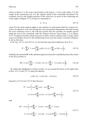
From Eqs. (15.7.1) and (15.7.2), we see that the equivalent unbalance force F is:
m n n
F* = F = mrω 2 ∑ cos(θ φ r ∑ cos ( 2 θ φ n ) (15.7.3)
+
*
+ ) +( ) l
∑ i i i y
= i 1 = i 1 = i 1
*
Similarly, the moment M of the unbalancing forces about the crankshaft point at the center
of the first cylinder is:
n n
M* = mrω 2 a ∑ (i − ) 1 cos(θ φ i r ∑ (i − ) 1 cos (θ φ i n z (15.7.4)
+ )
+ ) +( ) l
2
= i 1 = i 1
To explore the implications of these results, we can expand the terms on the right sides
of Eqs. (15.7.3) and (15.7.4) using the identity:
(
+
θ
cos θφ ) ≡ cos cosφ − sin sinφ i (15.7.5)
θ
i
i
Equations (15.7.3) and (15.7.4) then become:
n n
F* = mrω 2 cosθ ∑ cosφ − sinθ ∑ sinφ
= i 1 i = i 1 i
(15.7.6)
n
n
+( ) l cos θ ∑ cos φ i −( ) l sin θ ∑ sin φ i n y
r
2
2
2
r
2
= i 1 = i 1
and
n n
M* = mrω 2 a cosθ ∑ (i − ) 1 cosφ − sinθ ∑ (i − ) 1 sinφ
= i 1 i = i 1 i
(15.7.7)
n
n
+( ) l cos θ ∑ (i − ) 1 cos φ i −( ) l sin θ ∑ (i − ) 1 sin φ i n z
r
r
2
2
2
2
= i 1 = i 1 

