
Page 551 - Dynamics of Mechanical Systems
P. 551
0593_C15_fm Page 532 Tuesday, May 7, 2002 7:05 AM
532 Dynamics of Mechanical Systems
Here we see that both the resultant primary and secondary inertia forces are also
balanced, leaving the only unbalance with the resultant primary moments. Thus, we have
still further improvement in the balance.
These examples demonstrate the wide range of possibilities available to the engine
designer; however, the examples are not meant to be exhaustive. Many other practical
configurations are possible. The examples simply show that the crankshaft configuration
can have a significant effect upon the engine balance. In the following section, we will
extend these concepts and analyses to eight-cylinder engines.
15.10 Eight-Cylinder Engines: The Straight-Eight and the V-8
If we consider engines with eight cylinders the number of options for balancing increases
dramatically. The analysis procedure, however, is the same as in the foregoing section. To
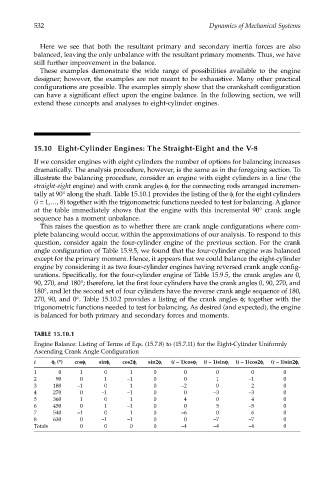
illustrate the balancing procedure, consider an engine with eight cylinders in a line (the
straight-eight engine) and with crank angles φ for the connecting rods arranged incremen-
i
tally at 90° along the shaft. Table 15.10.1 provides the listing of the φ for the eight cylinders
i
(i = 1,…, 8) together with the trigonometric functions needed to test for balancing. A glance
at the table immediately shows that the engine with this incremental 90° crank angle
sequence has a moment unbalance.
This raises the question as to whether there are crank angle configurations where com-
plete balancing would occur, within the approximations of our analysis. To respond to this
question, consider again the four-cylinder engine of the previous section. For the crank
angle configuration of Table 15.9.5, we found that the four-cylinder engine was balanced
except for the primary moment. Hence, it appears that we could balance the eight-cylinder
engine by considering it as two four-cylinder engines having reversed crank angle config-
urations. Specifically, for the four-cylinder engine of Table 15.9.5, the crank angles are 0,
90, 270, and 180°; therefore, let the first four cylinders have the crank angles 0, 90, 270, and
180°, and let the second set of four cylinders have the reverse crank angle sequence of 180,
270, 90, and 0°. Table 15.10.2 provides a listing of the crank angles φ; together with the
trigonometric functions needed to test for balancing. As desired (and expected), the engine
is balanced for both primary and secondary forces and moments.
TABLE 15.10.1
Engine Balance: Listing of Terms of Eqs. (15.7.8) to (15.7.11) for the Eight-Cylinder Uniformly
Ascending Crank Angle Configuration
i φφ φ φ i (°) cosφφ φφ i sinφφ φφ i cos2φφ φφ i sin2φφ φφ i (i – 1)cosφφ φφ i (i – 1)sinφφ φφ i (i – 1)cos2φφ φφ i (i – 1)sin2φφ φφ i
1 0 1 0 1 0 0 0 0 0
2 90 0 1 –1 0 0 1 –1 0
3 180 –1 0 1 0 –2 0 2 0
4 270 0 –1 –1 0 0 –3 –3 0
5 360 1 0 1 0 4 0 4 0
6 450 0 1 –1 0 0 5 –5 0
7 540 –1 0 1 0 –6 0 6 0
8 630 0 –1 –1 0 0 –7 –7 0
Totals 0 0 0 0 –4 –4 –4 0