
Page 125 - Electric Drives and Electromechanical Systems
P. 125
118 Electric Drives and Electromechanical Systems
Chapter 6, Brushless Motors and Controllers), with the switching between phases being
controlled by stator-mounted Hall-effect sensors. If the tachogenerator is integral to the
motor, the Hall-effect sensors can be used for both motor and tachogenerator control.
The maximum operational speed is only limited by the physical construction of the rotor
assembly. There are no moving parts other than the rotor; this leads to a high reliability
device, suitable for applications where maintenance is difficult, or not possible.
4.2.3 Incremental systems
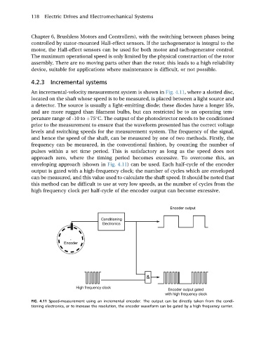
An incremental-velocity measurement system is shown in Fig. 4.11, where a slotted disc,
located on the shaft whose speed is to be measured, is placed between a light source and
a detector. The source is usually a light-emitting diode; these diodes have a longer life,
and are more rugged than filament bulbs, but can restricted be to an operating tem-
perature range of -10 to þ75 C. The output of the photodetector needs to be conditioned
prior to the measurement to ensure that the waveform presented has the correct voltage
levels and switching speeds for the measurement system. The frequency of the signal,
and hence the speed of the shaft, can be measured by one of two methods. Firstly, the
frequency can be measured, in the conventional fashion, by counting the number of
pulses within a set time period. This is satisfactory as long as the speed does not
approach zero, where the timing period becomes excessive. To overcome this, an
enveloping approach (shown in Fig. 4.11) can be used. Each half-cycle of the encoder
output is gated with a high-frequency clock; the number of cycles which are enveloped
can be measured, and this value used to calculate the shaft speed. It should be noted that
this method can be difficult to use at very low speeds, as the number of cycles from the
high frequency clock per half-cycle of the encoder output can become excessive.
FIG. 4.11 Speed-measurement using an incremental encoder. The output can be directly taken from the condi-
tioning electronics, or to increase the resolution, the encoder waveform can be gated by a high frequency carrier.