
Page 127 - Electric Drives and Electromechanical Systems
P. 127
120 Electric Drives and Electromechanical Systems
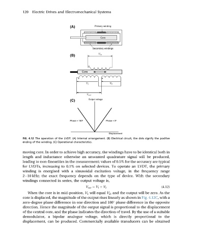
FIG. 4.12 The operation of the LVDT. (A) Internal arrangement. (B) Electrical circuit, the dots signify the positive
ending of the winding. (C) Operational characteristics.
moving core. In order to achieve high accuracy, the windings have to be identical both in
length and inductance otherwise an unwanted quadrature signal will be produced,
leading to non-linearities in the measurement; values of 0.5% for the accuracy are typical
for LVDTs, increasing to 0.1% on selected devices. To operate an LVDT, the primary
winding is energised with a sinusoidal excitation voltage, in the frequency range
2e10 kHz; the exact frequency depends on the type of device. With the secondary
windings connected in series, the output voltage is,
(4.12)
V out ¼ V 1 þ V 2
When the core is in mid-position, V 1 will equal V 2 , and the output will be zero. As the
core is displaced, the magnitude of the output rises linearly as shown in Fig. 4.12C,witha
zero-degree phase difference in one direction and 180 phase difference in the opposite
direction. Hence the magnitude of the output signal is proportional to the displacement
of the central core, and the phase indicates the direction of travel. By the use of a suitable
demodulator, a bipolar analogue voltage, which is directly proportional to the
displacement, can be produced. Commercially available transducers can be obtained