
Page 132 - Electric Drives and Electromechanical Systems
P. 132
Chapter 4 Velocity and position transducers 125
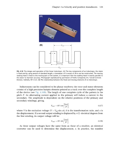
FIG. 4.16 The design and operation of the linear Inductosyn. (A) The key components of an Inductosyn, the stator
is fixed and by using several of standard length, a transducer of in excess of 10 m can be constructed. The moving
reading head is fixed to the moving part of the system, it is important that the reading head in exactly parallel to
the stator to maintain accuracy. Photograph reproduced by permission of Ruhle Companies, Inc. Farrad Controls
Division, Valhalla, NY U.S.A. (B) The relationship between the fixed and moving elements of an Inductosyn.
Inductosyns can be considered to be planar resolvers; the rotor and stator elements
consist of a high precision hairpin element printed as a track over the complete length
of the device (see Fig. 4.16B). The length of one complete cycle of the pattern is the
pitch P. An alternating current applied to the primary will induce a current in the
secondary. The amplitude is dependent on the relative positions of the primary and
secondary windings, giving.
2px
V out1 ¼ kV cos (4.17)
P
where V is the excitation voltage (V ¼ V pk sin ut), k is the transformation ratio, and x is
the displacement. If a second output winding is displaced by p/2 electrical degrees from
the first winding, its output voltage will be:
2px
V out2 ¼ kV sin (4.18)
P
As these output voltages have the same form as those of a resolver, an identical
converter can be used to determine the displacement, x. In practice, the number