
Page 134 - Electric Drives and Electromechanical Systems
P. 134
Chapter 4 Velocity and position transducers 127
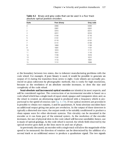
Table 4.2 Binary and grey codes that can be used in a four track
absolute optical position encoders.
State Pure binary Grey code
0 0000 0000
1 0001 0001
2 0010 0011
3 0011 0010
4 0100 0110
5 0101 0111
6 0110 0101
7 0111 0100
8 1000 1100
9 1001 1101
10 1010 1111
11 1011 1110
12 1100 1010
13 1101 1011
14 1110 1001
15 1111 1000
at the boundary between two states, due to inherent manufacturing problems with the
code wheel. For example, if pure binary is used, it would be possible to generate an
output of 15 during the transition from seven to eight. Code wheels are normally pro-
duced on glass substrates by photographic methods, this is costly for high resolutions,
because as the resolution of an absolute encoder increases, so does the size and
complexity of the code wheel.
Semi-absolute and incremental optical encoders are identical in most respects, and
will be considered together. The construction of an incremental encoder is based on a
code wheel which has a single track of equal-sized, opaque and transparent slots; and, as
the wheel is rotated, an alternating signal is produced with a frequency which is pro-
portional to the speed of rotation (see Fig. 4.17B). If two optical receivers are provided it
is possible to obtain two outputs, A and its quadrature, B. Semi-absolute encoders have
an additional output giving one pulse per revolution. As the output of these detectors is
typically a distorted sine wave, the output needs to be suitably conditioned to produce a
clean square wave for other electronic systems. This circuitry can be mounted in the
encoder or it can form part of the external system. As the resolution of the encoder
increases, the use of physical slots in the code wheel will become unreliable; hence, use
is made of optical gratings. As the code wheel is moved, the whole field observed by the
optical receiver goes dark as the lines move in and out of phase.
As previously discussed, an encoder with a single track will allow the magnitude of the
speed to be measured; the direction of rotation can be determined by the addition of a
second track or an additional sensor to produce a quadrature signal. The two signals