
Page 135 - Electric Drives and Electromechanical Systems
P. 135
128 Electric Drives and Electromechanical Systems
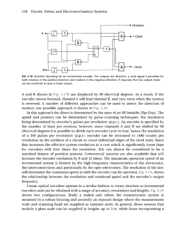
FIG. 4.18 Direction decoding for an incremental encoder. The outputs are direction, a clock signal is provided for
both rotation in the positive direction and rotation in the negative direction. If required, the two output clocks
can be combined to give a single output.
A and B shown in Fig. 4.17B are displaced by 90 electrical degrees. As a result, if the
encoder moves forward, channel A will lead channel B, and vice versa when the motion
is reversed. A number of different approaches can be used to detect the direction of
motion; one possible approach is shown in Fig. 4.18.
In this approach the direct is determined by the state of an SR bistable (flip-flop). The
speed and position can be determined by pulse-counting techniques, the resolution
being determined by encoder’s pulses per revolution (p.p.r.). An encoder is specified by
the number of lines per rotation; however, since channels A and B are shifted by 90
electrical degrees it is possible to divide each encoder cycle in four, hence the resolution
of a 360 pulses per revolution (p.p.r.) encoder can be increased to 1440 counts per
revolution by the addition of a circuit to count individual edges of the clock train. Since
this increases the effective system resolution at a cost which is significantly lower than
for encoders with four times the resolution, this can almost be considered to be a
standard feature of position systems. Commercial systems are also available that will
increase the encoder resolution by 8 and 12 times. The maximum operation speed of an
incremental system is limited by the high-frequency characteristics of the electronics,
the interconnections and particularly by the opto-electronics. The resolution of the disc
will determine the maximum speed at with the encoder can be operated, Fig. 4.19, shows
the relationship between the resolution and rotational speed and the encoder’s output
frequency.
Linear optical encoders operate in a similar fashion to rotary absolute or incremental
encoders and can be obtained with a range of accuracy, resolutions and lengths. Fig. 4.20
shows two configurations, firstly a sealed unit where the measurement system is
mounted in a robust housing and secondly an exposed design where the measurement
scale and scanning head are supplied as separate units. In general, those sensors that
include a glass scale can be supplied in lengths up to 3 m, while those incorporating a