
Page 140 - Electric Drives and Electromechanical Systems
P. 140
Chapter 4 Velocity and position transducers 133
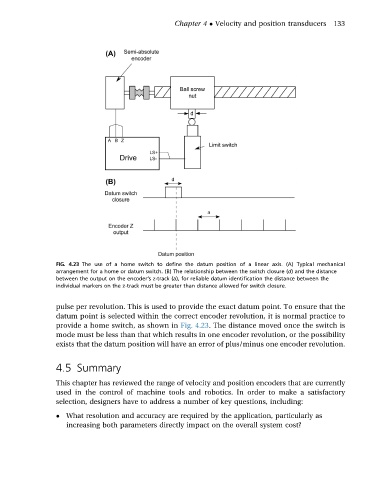
FIG. 4.23 The use of a home switch to define the datum position of a linear axis. (A) Typical mechanical
arrangement for a home or datum switch. (B) The relationship between the switch closure (d) and the distance
between the output on the encoder’s z-track (a), for reliable datum identification the distance between the
individual markers on the z-track must be greater than distance allowed for switch closure.
pulse per revolution. This is used to provide the exact datum point. To ensure that the
datum point is selected within the correct encoder revolution, it is normal practice to
provide a home switch, as shown in Fig. 4.23. The distance moved once the switch is
mode must be less than that which results in one encoder revolution, or the possibility
exists that the datum position will have an error of plus/minus one encoder revolution.
4.5 Summary
This chapter has reviewed the range of velocity and position encoders that are currently
used in the control of machine tools and robotics. In order to make a satisfactory
selection, designers have to address a number of key questions, including:
What resolution and accuracy are required by the application, particularly as
increasing both parameters directly impact on the overall system cost?