
Page 144 - Electric Drives and Electromechanical Systems
P. 144
Chapter 5 Brushed direct-current motors 137
1
is the speed of rotation (rad s ), K e is the motor’s speed constant (V rad 1 s), and K t is
1
the motor’s torque constant (Nm A ). V m is the motor’s terminal voltage.
The torque-speed envelope of a typical permanent-magnet motor is shown in
Fig. 5.1B; it exhibits good low-speed torque-ripple characteristics through to a standstill,
which makes it ideal for servo applications. However, the high-speed characteristics are
limited: as the rotational speed increases, the voltage between the commutator segments
also increases; and if this is combined with a high armature current (that is, a high
torque), a voltage breakdown between adjacent commutator segments will result in a
motor flash-over. The result will be considerable damage to the motor and its drive.
Therefore, the motor’s absolute operational area is bounded in practice by the peak
values of the armature current and the voltage (that is, the speed), and by the com-
mutation limit. In addition, within these constraints, the thermal limits of the motor will
dictate the area where continuous operation is possible; this area can be increased by the
addition of forced ventilation.
5.2 Direct-current motors
5.2.1 Ironless-rotor motors
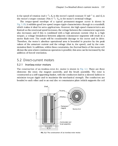
The construction of an ironless-rotor d.c. motor is shown in Fig. 5.2. There are three
elements: the rotor, the magnet assembly, and the brush assembly. The rotor is
constructed as a self-supporting basket, with the conductors laid in a skewed fashion to
minimise torque ripple and to maximise the mechanical strength. The conductors are
bonded to each other and to an end disc or commutator plate (which supports the coil
FIG. 5.2 The construction of an ironless-rotor motor.