
Page 137 - Electric Drives and Electromechanical Systems
P. 137
130 Electric Drives and Electromechanical Systems
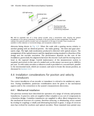
FIG. 4.21 An exploded view of a linear optical encoder using a transmissive scale, showing the general
arrangement of the optical components, the length of the optical path has been exaggerated. The detailed
coding of the graticule and the encoder track are dependent on the type of encoder; linear encoders are
available in either absolute or incremental design, and incorporate a datum track.
elements being shown in Fig. 4.21. When the scale with a grating moves relative to
another grating with an identical pattern - the index grating - the lines and gaps alter-
nately align. The light-dark modulation produced is detected with optical sensors. The
arrangement of the optical sensors and the signal processing required is a function of the
design and the encoder resolution. The performance depends on the care of the
installation, particularly the alignment between the encoder track and the moving sensor
head in the exposed design. Careful maintenance of the measurement system is
required, particularly in the case of a sealed unit, as the sensor can move up to 4000 km
per year. As with rotary encoders a reference mark is provided on a second track, parallel
to the incremental track, which are scanned, and used to locate the datum position, as
discussed in Section 4.4.3.
4.4 Installation considerations for position and velocity
transducers
The correct installation of an encoder or transducer is critical to its satisfactory opera-
tion. During installation, particular consideration must be given to the mechanical
aspects and to the connection to the system’s measurement electronics.
4.4.1 Mechanical installation
The previous sections have described the operation of a range of velocity and position
transducers. In practice, units are supplied either complete or as a set of components in
a frameless design. Frameless transducers are supplied to allow direct integration into
the mechanical structure of a system, therefore reducing, or eliminating, errors caused
by windup in couplings or shafts and eliminating backlash in gears. A range of common
sizes has evolved for resolvers and optical encoders. These standard sizes permit easy