
Page 138 - Electric Drives and Electromechanical Systems
P. 138
Chapter 4 Velocity and position transducers 131
interchangeability between manufacturers’ products. It should be noted that the shafts
can either be solid or hollow, giving designers a number of integrations options when
undertaking the design of a mechanical systems.
In coupling the motor or the load to a rotary transducer, care must be taken to ensure
that the respective shafts are correctly aligned in all axes; if they are not correctly aligned,
a considerable load will be placed on the transducer bearings, leading to premature
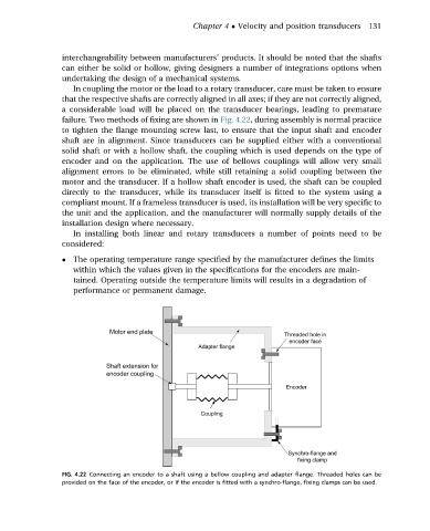
failure. Two methods of fixing are shown in Fig. 4.22, during assembly is normal practice
to tighten the flange mounting screw last, to ensure that the input shaft and encoder
shaft are in alignment. Since transducers can be supplied either with a conventional
solid shaft or with a hollow shaft, the coupling which is used depends on the type of
encoder and on the application. The use of bellows couplings will allow very small
alignment errors to be eliminated, while still retaining a solid coupling between the
motor and the transducer. If a hollow shaft encoder is used, the shaft can be coupled
directly to the transducer, while its transducer itself is fitted to the system using a
compliant mount. If a frameless transducer is used, its installation will be very specific to
the unit and the application, and the manufacturer will normally supply details of the
installation design where necessary.
In installing both linear and rotary transducers a number of points need to be
considered:
The operating temperature range specified by the manufacturer defines the limits
within which the values given in the specifications for the encoders are main-
tained. Operating outside the temperature limits will results in a degradation of
performance or permanent damage.
FIG. 4.22 Connecting an encoder to a shaft using a bellow coupling and adapter flange. Threaded holes can be
provided on the face of the encoder, or if the encoder is fitted with a synchro-flange, fixing clamps can be used.