
Page 130 - Electric Drives and Electromechanical Systems
P. 130
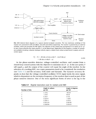
Chapter 4   Velocity and position transducers  123


                 FIG. 4.14 Internal block diagram of a typical resolver-to-digital converter. The two stationary windings of the
                 resolver are connected to SIN and SINLO, and COS and COSLO respectively. The resolver is powered by an external
                 oscillator, which also provides the REF signal. The objective of the closed loop arrangement is to reduce sin (q 4)
                 to zero, hence allowing the rotary position, q, to be determined. Depending of the supplier a number of outputs
                 are available including, a bipolar analogue velocity signal, a digital clock output proportional to speed, and a di-
                 rection signal.

                                        0   0
                                       V   V ¼ Ak sin utðcos 4 sin q   cos q sin 4Þ
                                        1   2
                                                                                            (4.16)
                                           ¼ Ak sin ut sinðq   4Þ
                   As the phase-sensitive detector, voltage-controlled oscillator, and counter form a
                 closed-loop control system with the objective to minimise sin (q 4). At the zero point, q
                 will equal 4, and the output of the counter will equal the angle of the resolver. In the
                 selection of a tracking RDC, two major parameters need to be considered: the resolution
                 (see Table 4.1) and the accuracy, both static and dynamic. The dynamic accuracy de-
                 pends on how fast the voltage-controlled oscillator (VCO) input tracks the error signal,
                 which is dependent on the excitation frequency of the resolver that is used as part of the
                 phase sensitive detector. One of the most significant forms of error is the lag in the


                         Table 4.1  Digital resolution over 2p radians and 360 .

                                                  Angle in radians         Angle in degrees
                         Number of bits           per bit                  per bit
                         1                        3.1415                   180.00
                         2                        1.5707                   90.00
                         4                        0.3927                   22.50
                         8                        0.02545                  1.4063
                         10                       0.00614                  0.3516
                         12                       0.001534                 0.08789
                         16                       0.000096                 0.00549