
Page 131 - Electric Drives and Electromechanical Systems
P. 131
124 Electric Drives and Electromechanical Systems
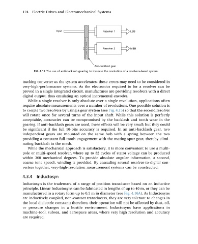
FIG. 4.15 The use of anti-backlash gearing to increase the resolution of a resolvers-based system.
tracking converter as the system accelerates; these errors may need to be considered in
very-high-performance systems. As the electronics required to for a resolver can be
proved in a single integrated circuit, manufactures are providing resolvers with a direct
digital output, thus emulating an optical incremental encoder.
While a single resolver is only absolute over a single revolution, applications often
requireabsolutemeasurementsover a number of revolutions. Onepossiblesolutionis
to coupletwo resolversbyusingagearsystem(see Fig. 4.15) so that the second resolver
will rotate once for several turns of the input shaft. While this solution is perfectly
acceptable, accuracies can be compromised by the backlash and tooth wear in the
gearing. If anti-backlash gears are used, these effects will be very small; but they could
be significant if the full 16-bits accuracy is required. In an anti-backlash gear, two
independent gears are mounted on the same hub with a spring between the two
providing a constant full-tooth engagement with the mating spur gear, thereby elimi-
nating backlash in the mesh.
While the mechanical approach is satisfactory, it is more convenient to use a multi-
pole or multi-speed resolver, where up to 32 cycles of stator voltage can be produced
within 360 mechanical degrees. To provide absolute angular information, a second,
coarse (one speed), winding is provided. By cascading several resolver-to-digital con-
verters together, very-high-resolution measurement systems can be constructed.
4.3.4 Inductosyn
Inductosyn is the trademark of a range of position transducer based on an inductive
principle. Linear Inductosyns can be fabricated in lengths of up to 40 m, or they can be
manufactured in arotaryformupto0.5 mindiameter(see Fig. 4.16A). As Inductosyns
are inductively coupled, non-contact transducers, they are very tolerant to changes in
the local dielectric constant; therefore, their operation will not be affected by dust, oil,
or pressure changes in a hostile environment. Inductosyns have applications in
machine-tool, subsea, and aerospace areas, where very high resolution and accuracy
are required.