
Page 194 - Electric Drives and Electromechanical Systems
P. 194
Chapter 7 Induction motors 189
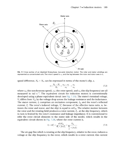
FIG. 7.1 Cross section of an idealised three-phase, two-pole induction motor. The rotor and stator windings are
represented as concentrated coils. The rotor’s speed is u r , and the lag between the rotor and stator axes is q r .
speed difference, N e e N r , can be expressed in terms of the motor’s slip, s,
N e N r u e u r u s
s ¼ ¼ ¼ (7.2)
N e u e u e
where u e (the synchronous speed), u r (the rotor speed), and u s (the slip frequency) are all
1
measured in rad s . The equivalent circuit for induction motors is conventionally
developed using a phase-equivalent circuit (see Fig. 7.1A). The stator’s terminal voltage,
V s differs from V m by the voltage drop across the leakage resistance and the inductance.
The stator current, I r comprises an excitation component, I m and the rotor’s reflected
current, I . The rotor’s induced voltage, V (because of the effective turns ratio, n, be-
0
0
r
r
tween the rotor and stator, and the slip) is equal to snV m . The relative motion between
the rotor and the rotating field produces a rotor current, I ., at the slip frequency, which
0
r
in turn is limited by the rotor’s resistance and leakage impedance. It is conventional to
refer the rotor circuit elements to the stator side of the model, which results in the
equivalent circuit shown in Fig. 7.2B, where the rotor current is,
2
n sV m V m
0
I r ¼ nI ¼ ¼ (7.3)
r
R þ ju s L 0 r R r
0
r
s þ ju e L r
The air-gap flux which is rotating at the slip frequency, relative to the rotor, induces a
voltage at the slip frequency in the rotor, which results in a rotor current; this current