
Page 196 - Electric Drives and Electromechanical Systems
P. 196
Chapter 7 Induction motors 191
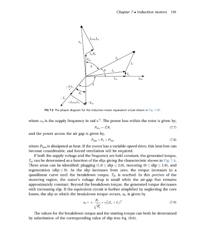
FIG 7.3 The phasor diagram for the induction motor equivalent circuit shown in Fig. 7.2B.
-1
where u s is the supply frequency in rad s . The power loss within the rotor is given by,
2
P loss ¼ I R r (7.7)
r
and the power across the air gap is given by,
(7.8)
P gap ¼ P o þ P loss
where P loss is dissipated as heat. If the motor has a variable-speed drive, this heat loss can
become considerable, and forced ventilation will be required.
If both the supply voltage and the frequency are held constant, the generated torque,
T e , can be determined as a function of the slip; giving the characteristic shown in Fig. 7.4.
Three areas can be identified: plugging (1.0 slip 2.0), motoring (0 slip 1.0), and
regeneration (slip 0). As the slip increases from zero, the torque increases in a
quasilinear curve until the breakdown torque, T b , is reached. In this portion of the
motoring region, the stator’s voltage drop is small while the air-gap flux remains
approximately constant. Beyond the breakdown torque, the generated torque decreases
with increasing slip. If the equivalent circuit is further simplified by neglecting the core
losses, the slip at which the breakdown torque occurs, s b , is given by
R r 2 2
ffiffiffiffiffi þ u ðL s þ L r Þ (7.9)
s b ¼ q e
R 2
s
The values for the breakdown torque and the starting torque can both be determined
by substitution of the corresponding value of slip into Eq. (9.6).