
Page 197 - Electric Drives and Electromechanical Systems
P. 197
192 Electric Drives and Electromechanical Systems
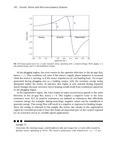
FIG. 7.4 Torque-speed curve for a 2-pole induction motor operating with a constant-voltage, 50 Hz supply, T s is
the starting torque, and T b is the breakdown torque.
In the plugging region, the rotor rotates in the opposite direction to the air-gap flux;
hence s > 1. This condition will arise if the stator’s supply phase sequence is reversed
while the motor is running, or if the motor experiences an overhauling load. The torque
generated during plugging acts as a braking torque, with the resultant energy being
dissipated within the motor. In practice, this region is only entered during transient
speed changes-because excessive motor heating would result from continuous operation
in the plugging region.
In the regenerative region, the rotor rotates at super-synchronous speeds in the same
direction as the air-gap flux, hence s < 0. This implies a negative value to the rotor
resistance term, R r /s As positive resistances are defined as resistances that effectively
consume energy (for example, during motoring), negative values can be considered to
generate energy. This energy flow will result in a negative or regenerative braking torque.
Since the energy is returned to the supply, the motor can remain in the regenerative
region for extended periods of time; this forms an important part of the control required
for an induction motor in variable-speed applications.
nnn
Example 7.1
Determine the starting torque, and breakdown slip and torque for a 2-pole delta wound in-
duction motor operating at 50 Hz. The motor’s parameters with reference to Fig. 7.2B are