
Page 202 - Electric Drives and Electromechanical Systems
P. 202
Chapter 7 Induction motors 197
vector-control system (also known as field oriented control) results in the motor’s tor-
que- and flux-producing current components being decoupled. This results in transient
response characteristics that are comparable to those of a separately excited motor.
Consider the d.c. motor torque equation,
(7.10)
T ¼ K t I a I f
where I a is the armature current, I f is the field current which is proportional to the
air-gap flux, and K t is the torque constant. In a conventional d.c. brushed-motor control
scheme, it is the air-gap flux that is held constant, and the armature current (and hence
the torque) is controlled. As the armature current is decoupled from the field current, the
motor’s torque sensitivity remains at its maximum value during both steady-state and
transient operations. This approach to decoupled control is not possible using a
scalar-control scheme applied to an induction motor.
In order to give servo-drive capabilities to induction motors, vector control has been
developed. The rationale for this approach can be appreciated from the phasor diagram
of an induction motor’s per-phase equivalent circuit (Fig. 7.3). The electrical torque can
be expressed as,
T e ¼ K T j m I r sin d (7.11)
where j m and I r are the root-mean-square (rms) values of the air-gap flux and the rotor
current, respectively. If the core losses are neglected, Eq. (7.11) can be further simplified
to,
0 0
T e ¼ K I m I s sin q ¼ K I m I a (7.12)
T
T
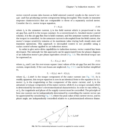
where (I a ¼ I s sinq) is the torque component of the stator current (see Fig. 7.8). As is
readily apparent, this torque equation is now in an identical form to the equation for d.c.
motor: I m is the magnetising or flux component of the stator current, and I a is the
armature or torque component of the stator current, while K T is a torque constant which
is determined by the motor’s electromechanical characteristics. In order to vary either I m
or I a , the magnitude and phase of the supply current must be controlled. The principle of
how one current can be independently determined by controlling the current vector can
be appreciated by considering Fig. 7.9, where the peak value of the current vector, and its
phase angle, are independently controlled relative to a predetermined reference frame.
FIG. 7.8 The relationship between Ia and Is as applied to vector control.