Page 204 - Electric Drives and Electromechanical Systems
P. 204

Chapter 7   Induction motors  199


                 balanced, three-phase, a.c. supply, then the conventional two-axis, or d-q, approach to
                 motor modelling can be used to analyse the operation of the induction motor. This
                 approach permits the time-varying motor parameters to be eliminated, and the motor
                 variables can be expressed relative to a set of mutually decoupled orthogonal axes, which
                 are commonly termed the direct and the quadrature axes.
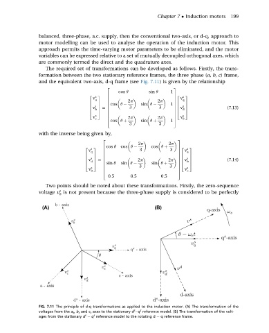
                   The required set of transformations can be developed as follows. Firstly, the trans-
                 formation between the two stationary reference frames, the three phase (a, b, c) frame,
                 and the equivalent two-axis, d-q frame (see Fig. 7.11) is given by the relationship
                                            2                          3
                                                cos q        sin q   1
                                     2  s  3  6                        7 v s  3
                                                                       72
                                      v a   6                             q
                                            6       2p          2p     7
                                             cos q       sin q
                                     6  7   6                        1  76  7
                                     6  s 7  6       3           3     76  s 7              (7.13)
                                                                          d
                                       b
                                     6 v 7 ¼ 6                         76 v 7
                                     4  5   6                          74  5
                                      v s   6       2p          2p     7  v s
                                            6
                                                                       7
                                       c                                  0
                                            4                        1  5
                                             cos q þ     sin q þ
                                                     3           3
                 with the inverse being given by,
                                          2                             3
                                                        2p           2p

                                          6 cos q  cos q      cos q þ
                                    v q   6                                 a
                                   2  s  3               3           3  7 v  s  3
                                                                        72
                                          6                             7
                                   6   7  6                             76   7

                                   6  s 7  6            2p               76  s 7            (7.14)
                                                                            b
                                     d
                                   6 v 7 ¼ 6                        2p 76 v 7
                                          6 sin q
                                   4   5          sin q    3  sin q þ  3  74  5
                                     v s  6                             7  v s
                                          6
                                                                        7
                                     0                                      c
                                          4                             5
                                            0:5      0:5          0:5
                   Two points should be noted about these transformations. Firstly, the zero-sequence
                         s
                 voltage v is not present because the three-phase supply is considered to be perfectly
                         0


                 FIG. 7.11 The principle of d-q transformations as applied to the induction motor. (A) The transformation of the
                                                       s
                                                         s
                 voltages from the a s , b s and c s axes to the stationary d  q reference model. (B) The transformation of the volt-
                                       s
                                   s
                 ages from the stationary d e q reference model to the rotating d e q reference frame.
   199   200   201   202   203   204   205   206   207   208   209