
Page 207 - Electric Drives and Electromechanical Systems
P. 207
202 Electric Drives and Electromechanical Systems
FIG. 7.13 The relative angles between the stationary and rotating axes, as used in the computation of the
transforms.
the slip angle, q s ,. These angles need to be determined in the implementation of indirect
vector control. For decoupled control, the stator’s flux component and the torque
component are aligned with the rotating d- and q-axes, respectively. As noted earlier, the
slip of an induction motor can be determined from the demanded rotor current; this fact
is used in indirect vector controllers to determine u s , for the demanded rotor current,
and then sinu s , and cosu s can be determined. The values of sin u r and cos u r can be
measured directly; if the induction motor is fitted with rotary position encoder, both
these angles can then be used to determine sin u e and cos u e , as required by the axes
transformations. This approach does, however, require that the parameters of the motor
have been accurately determined during manufacture or as part of the commissioning
procedure.
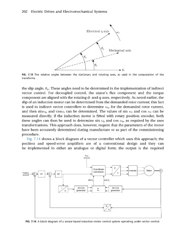
Fig. 7.14 shows a block diagram of a vector controller which uses this approach; the
position and speed-error amplifiers are of a conventional design and they can
be implemented in either an analogue or digital form; the output is the required
FIG. 7.14 A block diagram of a sensor-based induction-motor control system operating under vector control.