
Page 206 - Electric Drives and Electromechanical Systems
P. 206
Chapter 7 Induction motors 201
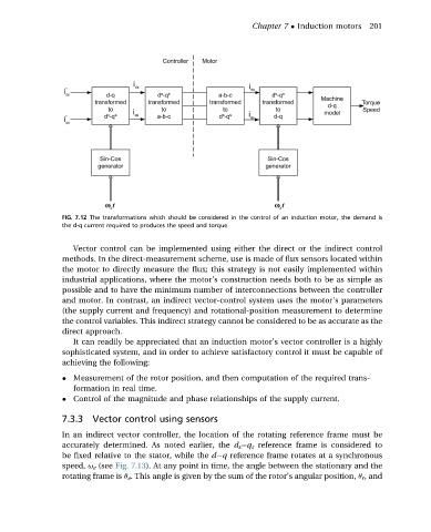
FIG. 7.12 The transformations which should be considered in the control of an induction motor, the demand is
the d-q current required to produces the speed and torque.
Vector control can be implemented using either the direct or the indirect control
methods. In the direct-measurement scheme, use is made of flux sensors located within
the motor to directly measure the flux; this strategy is not easily implemented within
industrial applications, where the motor’s construction needs both to be as simple as
possible and to have the minimum number of interconnections between the controller
and motor. In contrast, an indirect vector-control system uses the motor’s parameters
(the supply current and frequency) and rotational-position measurement to determine
the control variables. This indirect strategy cannot be considered to be as accurate as the
direct approach.
It can readily be appreciated that an induction motor’s vector controller is a highly
sophisticated system, and in order to achieve satisfactory control it must be capable of
achieving the following:
Measurement of the rotor position, and then computation of the required trans-
formation in real time.
Control of the magnitude and phase relationships of the supply current.
7.3.3 Vector control using sensors
In an indirect vector controller, the location of the rotating reference frame must be
accurately determined. As noted earlier, the d s q s reference frame is considered to
be fixed relative to the stator, while the d q reference frame rotates at a synchronous
speed, u e (see Fig. 7.13). At any point in time, the angle between the stationary and the
rotating frame is q e . This angle is given by the sum of the rotor’s angular position, q r , and