
Page 210 - Electric Drives and Electromechanical Systems
P. 210
Chapter 7 Induction motors 205
7.4 Matrix converter
In all the control systems described above, the a.c. supply to the induction motor was
generated using a conventional rectifier-inverter or d.c. link inverter arrangement.
Recently research has been undertaken on an a.c. - a.c. converter design that is capable
of giving compatible performance to the d.c. link inverter (Wheeler et al., 2002).
The matrix converter uses nine bidirectional switches to generate the output waveform.
The use of a matrix converter allows the removal of the d.c. rectifier and the link
capacitors, hence reducing the volume, enhances the system’s efficiency, increases the
reliability and simplifying the control schemes. In addition this approach only
requires small filters to suppress the ripples generated by the switching actions
(Zhang et al., 2018).
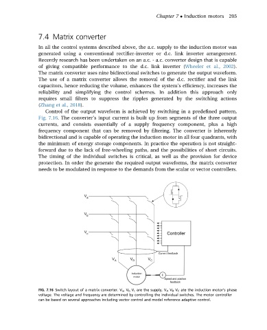
Control of the output waveform is achieved by switching in a predefined pattern,
Fig. 7.16. The converter’s input current is built up from segments of the three output
currents, and consists essentially of a supply frequency component, plus a high
frequency component that can be removed by filtering. The converter is inherently
bidirectional and is capable of operating the induction motor in all four quadrants, with
the minimum of energy storage components. In practice the operation is not straight-
forward due to the lack of free-wheeling paths, and the possibilities of short circuits.
The timing of the individual switches is critical, as well as the provision for device
protection. In order the generate the required output waveforms, the matrix converter
needs to be modulated in response to the demands from the scalar or vector controllers.
FIG. 7.16 Switch layout of a matrix converter. V a ,V b V c are the supply, V A V B V C ate the induction motor’s phase
voltage. The voltage and frequency are determined by controlling the individual switches. The motor controller
can be based on several approaches including vector control and model reference adaptive control.