
Page 215 - Electric Drives and Electromechanical Systems
P. 215
Chapter 8 Stepper motors 211
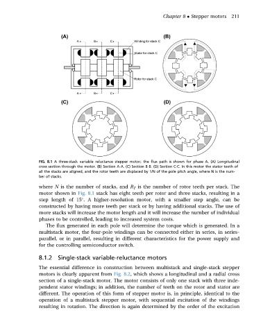
FIG. 8.1 A three-stack variable reluctance stepper motor; the flux path is shown for phase A. (A) Longitudinal
cross section through the motor. (B) Section A-A. (C) Section B-B. (D) Section C-C. In this motor the stator teeth of
all the stacks are aligned, and the rotor teeth are displaced by 1/N of the pole pitch angle, where N is the num-
ber of stacks.
where N is the number of stacks, and R T is the number of rotor teeth per stack. The
motor shown in Fig. 8.1 stack has eight teeth per rotor and three stacks, resulting in a
step length of 15 . A higher-resolution motor, with a smaller step angle, can be
constructed by having more teeth per stack or by having additional stacks. The use of
more stacks will increase the motor length and it will increase the number of individual
phases to be controlled, leading to increased system costs.
The flux generated in each pole will determine the torque which is generated. In a
multistack motor, the four-pole windings can be connected either in series, in series-
parallel, or in parallel, resulting in different characteristics for the power supply and
for the controlling semiconductor switch.
8.1.2 Single-stack variable-reluctance motors
The essential difference in construction between multistack and single-stack stepper
motors is clearly apparent from Fig. 8.2, which shows a longitudinal and a radial cross
section of a single-stack motor. The motor consists of only one stack with three inde-
pendent stator windings; in addition, the number of teeth on the rotor and stator are
different. The operation of this form of stepper motor is, in principle, identical to the
operation of a multistack stepper motor, with sequential excitation of the windings
resulting in rotation. The direction is again determined by the order of the excitation