
Page 217 - Electric Drives and Electromechanical Systems
P. 217
Chapter 8 Stepper motors 213
which results in a degree of mutual coupling between the phases and reduces the
performance of the motor in comparison with an equivalent multistack motor.
8.1.3 Hybrid stepper motors
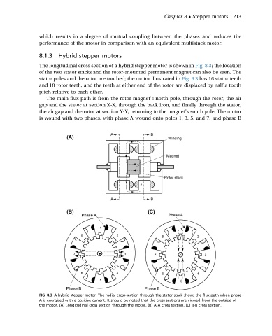
The longitudinal cross section of a hybrid stepper motor is shown in Fig. 8.3; the location
of the two stator stacks and the rotor-mounted permanent magnet can also be seen. The
stator poles and the rotor are toothed; the motor illustrated in Fig. 8.3 has 16 stator teeth
and 18 rotor teeth, and the teeth at either end of the rotor are displaced by half a tooth
pitch relative to each other.
The main flux path is from the rotor magnet’s north pole, through the rotor, the air
gap and the stator at section X-X, through the back iron, and finally through the stator,
the air gap and the rotor at section Y-Y, returning to the magnet’s south pole. The motor
is wound with two phases, with phase A wound onto poles 1, 3, 5, and 7, and phase B
FIG. 8.3 A hybrid stepper motor. The radial cross-section through the stator stack shows the flux path when phase
A is energised with a positive current. It should be noted that the cross sections are viewed from the outside of
the motor. (A) Longitudinal cross section through the motor. (B) A-A cross section. (C) B-B cross section.