
Page 214 - Electric Drives and Electromechanical Systems
P. 214
210 Electric Drives and Electromechanical Systems
A holding torque can be applied to the load solely with direct-current (d.c.) excita-
tion of the stepper motor’s windings.
The operation of stepper motors and their associated drive circuits are effectively
digital, permitting a relatively simple interface to a digital controller or to a
computer.
The mechanical construction of stepper motors is both simple and robust, leading
to high mechanical reliability.
8.1 Principles of stepper-motor operation
The essential feature of a stepper motor is its ability to translate the changes in stator
winding’s excitation into precisely defined changes, steps, of the rotor’s position
(Acarnley, 2002; Hughes and Drury, 2013). The positioning is achieved by the magnetic
alignment between the teeth of a stepper motor’s stator and rotor. There is a wide range
of stepper motors on the market, but they are all variations of two basic designs:
variable-reluctance stepper motors or hybrid stepper motors. Variable-reluctance
stepper motors can be also found as either multistack or single-stack motors. In the
variable-reluctance design, the magnetic flux is provided solely by stator excitation,
whereas the hybrid design uses the interaction between the magnetic flux produced by a
rotor-mounted permanent magnet and that resulting from the stator winding’s excitation.
8.1.1 Multistack variable-reluctance motors
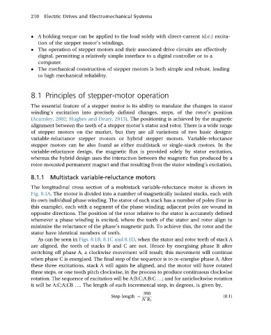
The longitudinal cross section of a multistack variable-reluctance motor is shown in
Fig. 8.1A. The motor is divided into a number of magnetically isolated stacks, each with
its own individual phase winding. The stator of each stack has a number of poles (four in
this example), each with a segment of the phase winding; adjacent poles are wound in
opposite directions. The position of the rotor relative to the stator is accurately defined
whenever a phase winding is excited, where the teeth of the stator and rotor align to
minimise the reluctance of the phase’s magnetic path. To achieve this, the rotor and the
stator have identical numbers of teeth.
As can be seen in Figs. 8.1B, 8.1C and 8.1D, when the stator and rotor teeth of stack A
are aligned, the teeth of stacks B and C are not. Hence by energising phase B after
switching off phase A, a clockwise movement will result; this movement will continue
when phase C is energised. The final step of the sequence is to re-energise phase A. After
these three excitations, stack A will again be aligned, and the motor will have rotated
three steps, or one tooth pitch clockwise, in the process to produce continuous clockwise
rotation. The sequence of excitation will be A:B:C:A:B:C .; and for anticlockwise rotation
it will be A:C:A:CB .. The length of each incremental step, in degrees, is given by,
360
Step length ¼ (8.1)
NR T