
Page 218 - Electric Drives and Electromechanical Systems
P. 218
214 Electric Drives and Electromechanical Systems
wound onto poles 2, 4, 6, and 8. Hence when phase A carries positive current stator poles
1 and 5 are magnetized as south, and poles 3 and 7 become north. The teeth on the north
end of the rotor are attracted to poles 1 and 5 while the offset teeth at the south end of
the rotor are attracted into line with the teeth on poles 3 and 7. For each winding, two
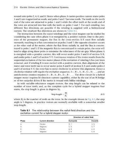
different flux directions are possible if the winding is supplied with a bidirectional
current. The resultant flux directions are shown in Table 8.1.
The interaction between the stator windings and the rotor magnet can be studied by
considering the case when phase A is energised by a positive current. Due to the pres-
ence of the permanent magnet, the flux in the cross-section X-X must flow radially
outwards, resulting in a flux concentration at poles 3 and 7; the opposite situation occurs
at the other end of the motor, where the flux flows radially in, and the flux is concen-
trated in poles 1 and 5. If the magnetic flux is concentrated in certain poles, the rotor will
tend to align along these poles to minimise the reluctance of the air-gap. When phase A
is energised with a positive current, this will occur under poles 3 and 8 of section X-X,
and under poles 1 and 5 of section Y-Y. Continuous rotation of the motor results from the
sequential excitation of the two motor phases if the excitation of winding A has just been
removed. and if winding B is now excited with a positive current, then alignment of the
stator and rotor teeth has to occur under poles 4 and 8 of section X-X and under poles 2
and 6 of section Y-Y; the rotor has to move clockwise to achieve this alignment. Hence a
clockwise rotation will require the excitation sequence, Aþ,Bþ, A-, B-, Aþ,Bþ ., and an
anticlockwise rotation requires Aþ, B-, A-, Bþ,Aþ, B -. . . . The drive circuit for a hybrid
stepper motor requires bi-direction-current capability, either by the use of an H-bridge
or of two unipolar drives if the motor is wound with bifilar windings.
As with variable-reluctance stepper motors, the step length can be related to the
number of rotor teeth, and, as the complete cycle for a hybrid stepper requires four
states, the step length is given in degrees by,
90
Step length ¼ (8.3)
R T
where R T is the number of teeth on the rotor. In the example shown in Fig. 8.3, the step
angle is 5 degrees, in practice motors are normally available with a somewhat smaller
step-length.
Table 8.1 The relationship between the radial-field direction and the
excitation current for a hybrid stepper motor.
Direction of radial field
Phase Current direction Outwards Inwards
A Positive 3, 7 1, 5
A Negative 1, 5 3, 7
B Positive 4, 8 2, 6
B Negative 2, 6 4, 8