
Page 200 - Electric Drives and Electromechanical Systems
P. 200
Chapter 7 Induction motors 195
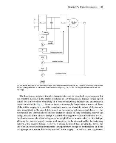
FIG. 7.6 Block diagram of the variable-voltage, variable-frequency inverter: F is a function generator that defines
the link voltage demand as a function of the inverter frequency; G1, G2 and G3 are gain blocks within the con-
trol loops.
The function generator’s transfer characteristic can be modified to compensate for
the effective increase in the stator resistance at low frequencies. Typical torque-speed
curves for a motor-drive consisting of a variable-frequency inverter and an induction
motor are shown in Fig. 7.7. Since an inverter can supply frequencies in excess of those
of the utility supply, it is possible to operate motors at speeds in excess of the motor’s
base speed (that is, the speed determined by the rated supply frequency); however, the
mechanical and thermal effects of such operation should be fully considered early in the
design process. If the inverter bridge is controlled using pulse-width modulation (PWM),
the direct-current (d.c.) link voltage can be supplied by an uncontrolled rectifier bridge,
allowing the motor’s supply voltage and frequency to be determined by the switching
pattern of the inverter bridge. However, it should be noted that, as with d.c. drives, the
use of an uncontrolled rectifier requires the regenerative energy to be dissipated by a bus
voltage regulator, rather than being returned to the supply. The method used to generate