
Page 195 - Electric Drives and Electromechanical Systems
P. 195
190 Electric Drives and Electromechanical Systems
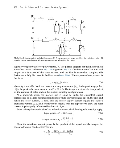
FIG. 7.2 Equivalent circuit of an induction motor. (A) A transformer per phase model of the induction motor. (B)
Induction motor model where all rotor components are referred to the stator.
lags the voltage by the rotor power factor, q r . The phasor diagram for the motor whose
equivalent circuit is shown in Fig. 7.2B is given in Fig. 7.3. The derivation of the electrical
torque as a function of the rotor current and the flux is somewhat complex; this
derivation is fully discussed in the literature (Bose, 2006). The torque can be expressed in
the form
T e ¼ K T j j m j I r sin d (7.4)
b
where K T is the effective induction-motor torque constant, jj m j is the peak air-gap flux,
I r is the peak value rotor current, and d ¼ 90 þ q r . The torque constant, K T , is dependent
b
on the number of poles and on the motor’s winding configurations.
At a standstill, when the motor’s slip is equal to unity, the equivalent circuit
corresponds to a short-circuited transformer; while at synchronous speed, the slip, and
hence the rotor current, is zero, and the motor supply current equals the stator’s
excitation current, I 0 . At sub-synchronous speeds, with the slip close to zero, the rotor
current is principally influenced by the ratio R r /s.
From this equivalent circuit of the induction motor, the following relationships apply,
Input power ¼ P i ¼ 3V s I s cos f (7.5a)
2
3I R r ð1 sÞ
r
Output power ¼ P o ¼ (7.5b)
s
Since the rotational output power is the product of the speed and the torque, the
generated torque can be expressed as,
2 2
P o 3 I R r ð1 sÞ 3I R r p
r
r
T e ¼ ¼ ¼ (7.6)
u r su r su s