
Page 247 - Electric Drives and Electromechanical Systems
P. 247
244 Electric Drives and Electromechanical Systems
is worthwhile first considering an analogue control system, before discussing the
implementation of a digital control system. To this end, the analysis of a single axis
based on a direct-current (d.c.) brushed motor will be undertaken as a continuous-time
system; the equivalent circuit of a d.c. brushed motor has been fully discussed in Chapter
5. The objective of the control loop is to hold the output position, q L , as close as possible
d
to the demanded position, q . If another motor is used then the control loop, and a
L
suitable transfer function for the drive and the motor, will need to be developed to
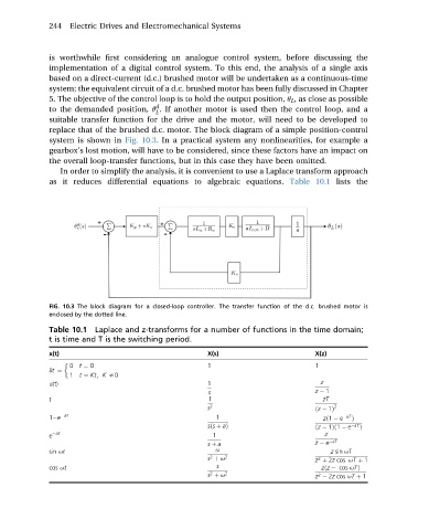
replace that of the brushed d.c. motor. The block diagram of a simple position-control
system is shown in Fig. 10.3. In a practical system any nonlinearities, for example a
gearbox’s lost motion, will have to be considered, since these factors have an impact on
the overall loop-transfer functions, but in this case they have been omitted.
In order to simplify the analysis, it is convenient to use a Laplace transform approach
as it reduces differential equations to algebraic equations. Table 10.1 lists the
FIG. 10.3 The block diagram for a closed-loop controller. The transfer function of the d.c. brushed motor is
enclosed by the dotted line.
Table 10.1 Laplace and z-transforms for a number of functions in the time domain;
t is time and T is the switching period.
x(t) X(s) X(z)
0 t ¼ 0 1 1
dt ¼
1 t ¼ Kt; K s0
u(t) 1 z
s z 1
t 1 zT
s 2 ðz 1Þ 2
1 e at 1 zð1 e aT Þ
sðs þ aÞ ðz 1Þð1 e aT Þ
e at 1 z
s þ a z e aT
sin ut u z sin uT
2
s þ u 2 z þ 2z cos uT þ 1
2
cos ut s zðz cos uTÞ
2
s þ u 2 z 2z cos uT þ 1
2