
Page 249 - Electric Drives and Electromechanical Systems
P. 249
246 Electric Drives and Electromechanical Systems
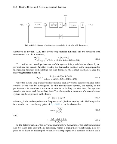
FIG. 10.4 Block diagram of a closed-loop control of a single joint with disturbances.
discussed in Section 1.2.1. The closed-loop transfer function can be rewritten with
reference to the disturbance as,
K t ðK p þ sK v Þ
Q L ðsÞ
¼ (10.5)
d
T d ðsÞ Q ðsÞ¼0 s R a I tot þ sðR a B þ K e K t þ K t K v Þþ K t K p
2
L
To consider the overall performance of the system, it is possible to combine, by su-
perposition, the transfer function relating the demanded position to the output position
the transfer function with relating the load torque to the output position, to give the
following transfer function,
d
K t K p þ sK v Q ðsÞR a T d ðsÞ
L
Q L ðsÞ¼ (10.6)
2
s R a I tot þ sðR a B þ K e K t þ K t K v Þþ K t K p
Once the closed-loop transfer equations have been developed the performance of the
control system can be investigated. In this second-order system, the quality of the
performance is based on a number of criteria, including the rise time, the system’s
steady-state error, and the settling time. The characteristic equation of a second-order
system can be expressed in the form,
2
2
s þ 2zu n s þ u ¼ 0 (10.7)
n
where u n is the undamped natural frequency and z is the damping ratio. If this equation
is related to the closed-loop poles of Eq. (10.6) it can be shown that,
s ffiffiffiffiffiffiffiffiffiffiffiffiffiffiffi
K t K p
u n ¼ (10.8)
I tot R a
and,
R a B þ K t K e þ K t K V
z ¼ (10.9)
2u n I tot R a
In the determination of the servo loop parameters, the nature of the application must
also be taken into account. In particular, within a manipulator application, it is not
possible to have an undamped response to a step input or a possible collision could