
Page 245 - Electric Drives and Electromechanical Systems
P. 245
242 Electric Drives and Electromechanical Systems
tool and robotics industries it is the practice for such controllers are normally
purchased by an original equipment manufacturer, OEM, for installation within
their own product.
Programmable logic controllers can control the logical operation of a process, and
they are capable of interfacing between the user, the external input/outputs, and
the motor-drive system. While the operation and function of PLCs is totally
different from the controllers associated with motion control, PLCs can be crucial
to overall system control and they hence need to be considered in any discussion
of modern industrial controllers.
10.1 Servo control
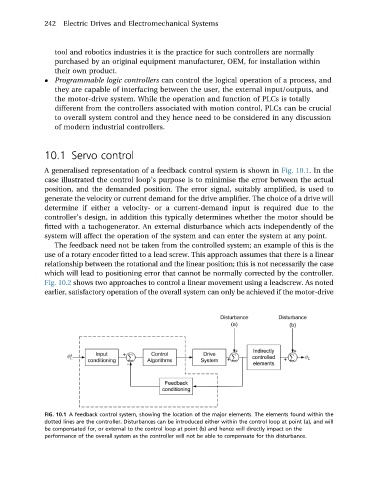
A generalised representation of a feedback control system is shown in Fig. 10.1. In the
case illustrated the control loop’s purpose is to minimise the error between the actual
position, and the demanded position. The error signal, suitably amplified, is used to
generate the velocity or current demand for the drive amplifier. The choice of a drive will
determine if either a velocity- or a current-demand input is required due to the
controller’s design, in addition this typically determines whether the motor should be
fitted with a tachogenerator. An external disturbance which acts independently of the
system will affect the operation of the system and can enter the system at any point.
The feedback need not be taken from the controlled system; an example of this is the
use of a rotary encoder fitted to a lead screw. This approach assumes that there is a linear
relationship between the rotational and the linear position; this is not necessarily the case
which will lead to positioning error that cannot be normally corrected by the controller.
Fig. 10.2 shows two approaches to control a linear movement using a leadscrew. As noted
earlier, satisfactory operation of the overall system can only be achieved if the motor-drive
FIG. 10.1 A feedback control system, showing the location of the major elements. The elements found within the
dotted lines are the controller. Disturbances can be introduced either within the control loop at point (a), and will
be compensated for, or external to the control loop at point (b) and hence will directly impact on the
performance of the overall system as the controller will not be able to compensate for this disturbance.