
Page 240 - Electric Drives and Electromechanical Systems
P. 240
236 Electric Drives and Electromechanical Systems
under closed loop control, with a shaft mounted encoder being used to synchronise the
phase currents with rotor position. In comparison, the variable-reluctance stepper motor
is operated open loop, with the principle design parameter being the accuracy of the
steps (Miller, 2001).
A detailed analysis of the switched inductance motor can be found in Miller (1989),
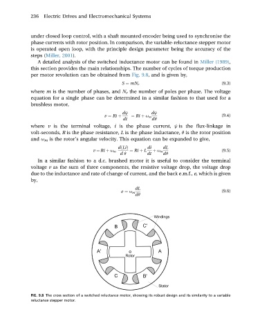
this section provides the main relationships. The number of cycles of torque production
per motor revolution can be obtained from Fig. 9.8, and is given by,
(9.3)
S ¼ mN r
where m is the number of phases, and N r the number of poles per phase. The voltage
equation for a single phase can be determined in a similar fashion to that used for a
brushless motor,
dj dj
v ¼ Ri þ ¼ Ri þ u m (9.4)
dt dq
where v is the terminal voltage, i is the phase current, j is the flux-linkage in
volt-seconds, R is the phase resistance, L is the phase inductance, q is the rotor position
and u m is the rotor’s angular velocity. This equation can be expanded to give,
dðLiÞ di dL
v ¼ Ri þ u m ¼ Ri þ L þ u m (9.5)
d q dt dq
In a similar fashion to a d.c. brushed motor it is useful to consider the terminal
voltage v as the sum of three components, the resistive voltage drop, the voltage drop
due to the inductance and rate of change of current, and the back e.m.f., e, which is given
by,
dL
e ¼ u m (9.6)
dq
FIG. 9.8 The cross section of a switched reluctance motor, showing its robust design and its similarity to a variable
reluctance stepper motor.