
Page 236 - Electric Drives and Electromechanical Systems
P. 236
232 Electric Drives and Electromechanical Systems
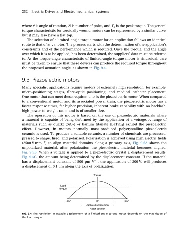
where q is angle of rotation, N is number of poles, and T p is the peak torque. The general
torque characteristic for toroidally wound motors can be represented by a similar curve,
but it may also have a flat top.
The selection of a limited-angle torque motor for an application follows an identical
route to that of any motor. The process starts with the determination of the application’s
constraints and of the performance which is required. Once the torque, and the angle
over which it is to be applied, has been determined, the suppliers’ data must be referred
to. As the torque-angle characteristic of limited-angle torque motor is sinusoidal, care
must be taken to ensure that these devices can produce the required torque throughout
the proposed actuation angle, as shown in Fig. 9.4.
9.3 Piezoelectric motors
Many specialist applications require motors of extremely high resolution, for example,
micro-positioning stages, fibre-optic positioning, and medical catheter placement.
One motor that can meet these requirements is the piezoelectric motor. When compared
to a conventional motor and its associated power train, the piezoelectric motor has a
faster response times, far higher precision, inherent brake capability with no backlash,
high power-to-weight ratio, and is of smaller size.
The operation of this motor is based on the use of piezoelectric materials where
a material is capable of being deformed by the application of a voltage. A range of
materials such as quartz (SiO 2 ) or barium titanate (BaTiO 3 ) exhibit the piezoelectric
effect. However, in motors normally mass-produced polycrystalline piezoelectric
ceramic is used. To produce a suitable ceramic, a number of chemicals are processed,
pressed to shape, fired, and polarised. Polarisation is achieved using high electric fields
1
(2500 V mm ) to align material domains along a primary axis, Fig. 9.5A shows the
unpolarized material, after polarization the piezoelectric material becomes aligned,
Fig. 9.5B. When a voltage is applied to a piezoelectric crystal a displacement results,
Fig. 9.5C, the amount being determined by the displacement constant. If the material
1
has a displacement constant of 500 pm V , the application of 200 V, will produces
a displacement of 0.1 mm along the axis of polarization.
FIG. 9.4 The restriction in useable displacement of a limited-angle torque motor depends on the magnitude of
the load torque.