
Page 239 - Electric Drives and Electromechanical Systems
P. 239
Chapter 9 Related motors and actuators 235
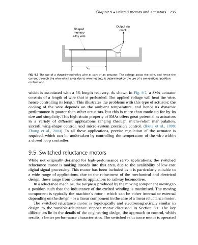
FIG. 9.7 The use of a shaped-metal-alloy wire as part of an actuator. The voltage across the wire, and hence the
current through the wire which gives rise to wire heating, is determined by the use of a conventional position
control loop.
which is associated with a 5% length recovery. As shown in Fig. 9.7, a SMA actuator
consists of a length of wire that is preloaded. The applied voltage will heat the wire,
hence controlling its length. This illustrates the problems with this type of actuator; the
cooling of the wire depends on the ambient temperature, and hence its dynamic
performance is poorer than other actuators, but this is more than made up for by its
size and simplicity. This high strain property of SMAs offers great potential as actuators
in a variety of different applications ranging through micro-robot manipulation,
aircraft wing-shape control, and micro-system precision control, (Ikuta et al., 1998;
Zhang et al., 2004). In all these applications, precise regulation of the actuator is
required, which can be undertaken by controlling the temperature of the wire within
a closed loop controller.
9.5 Switched reluctance motors
While not originally designed for high-performance servo applications, the switched
reluctance motor is making inroads into this area, due to the availability of low-cost
digital signal processing. This motor has been included as it is particularly suitable to
a wide range of applications, due to the robustness of the mechanical and electrical
design, these range from domestic appliances to railway locomotives.
In a reluctance machine, the torque is produced by the moving component moving to
a position such that the inductance of the excited winding is maximised. The moving
component is typically the machine’s rotor - which can be either internal or external
depending on the design - or a linear component in the case of a linear reluctance motor.
The switched reluctance motor is topologically and electromagnetically similar in
design to the variable-reluctance stepper motor discussed in Section 8.1. The key
differences lie in the details of the engineering design, the approach to control, which
results is better performance characteristics. The switched reluctance motor is operated