
Page 241 - Electric Drives and Electromechanical Systems
P. 241
Chapter 9 Related motors and actuators 237
From Eq. (9.5) it is possible to calculate that the instantaneous electrical power, vi,is
given by,
di dL
2
vi ¼ Ri þ Li þ u m i 2 (9.7)
dt dq
which allows the rate of change in magnetic energy to be calculated:
d 1 2 1 2 dL di
Li ¼ i u m ¼ Li (9.8)
dt 2 2 d q dt
The electromagnetic torque generated by the motor can therefore be determined
from the instantaneous electrical power minus the resistive voltages drops due and the
rate of change of magnetic stored energy:
d 1
2 2
vi Ri Li
dt 2 1 2 dL (9.9)
T e ¼ ¼ i
u m 2 d q
The rate of change of inductance as a function of rotor position is one of the design
parameters of the switched reluctance machine. From Eq. (9.9) it is shown that the
torque does not depend on the direction of current flow, however the voltage must be
reversed to reduce the flux-linkage to zero. A suitable power circuit for a single winding is
shown in Fig. 9.8, this circuit is far more robust that the conventional PWM bridge design
discussed earlier, as a line-to-line short circuit is not possible.
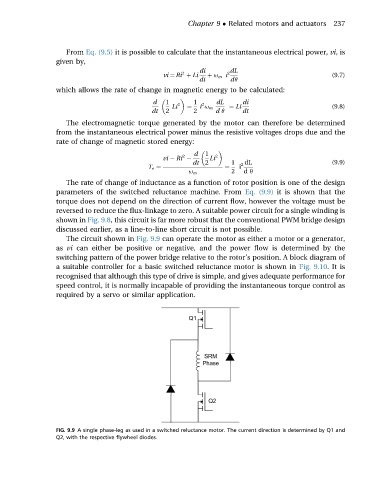
The circuit shown in Fig. 9.9 can operate the motor as either a motor or a generator,
as vi can either be positive or negative, and the power flow is determined by the
switching pattern of the power bridge relative to the rotor’s position. A block diagram of
a suitable controller for a basic switched reluctance motor is shown in Fig. 9.10.Itis
recognised that although this type of drive is simple, and gives adequate performance for
speed control, it is normally incapable of providing the instantaneous torque control as
required by a servo or similar application.
FIG. 9.9 A single phase-leg as used in a switched reluctance motor. The current direction is determined by Q1 and
Q2, with the respective flywheel diodes.