
Page 252 - Electric Drives and Electromechanical Systems
P. 252
Chapter 10 Controllers for automation 249
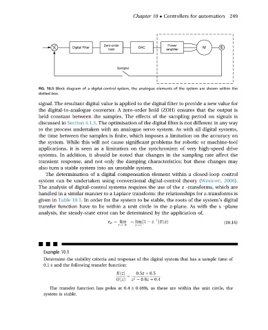
FIG. 10.5 Block diagram of a digital-control system, the analogue elements of the system are shown within the
dotted box.
signal. The resultant digital value is applied to the digital filter to provide a new value for
the digital-to-analogue converter. A zero-order hold (ZOH) ensures that the output is
held constant between the samples. The effects of the sampling period on signals is
discussed in Section 4.1.3. The optimisation of the digital filter is not different in any way
to the process undertaken with an analogue servo system. As with all digital systems,
the time between the samples is finite, which imposes a limitation on the accuracy on
the system. While this will not cause significant problems for robotic or machine-tool
applications, it is seen as a limitation on the synchronism of very high-speed drive
systems. In addition, it should be noted that changes in the sampling rate affect the
transient response, and not only the damping characteristics; but these changes may
also turn a stable system into an unstable system.
The determination of a digital compensation element within a closed-loop control
system can be undertaken using conventional digital-control theory (Westcott, 2006).
The analysis of digital-control systems requires the use of the z -transforms, which are
handled in a similar manner to a Laplace transform: the relationships for z-transforms is
given in Table 10.1. In order for the system to be stable, the roots of the system’s digital
transfer function have to lie within a unit circle in the z-plane. As with the s -plane
analysis, the steady-state error can be determined by the application of,
1
e ss ¼ lim ¼ lim 1 z EðzÞ (10.16)
t/ N z/1
nnn
Example 10.1
Determine the stability criteria and response of the digital system that has a sample time of
0.1 s and the following transfer function:
XðzÞ 0:5z þ 0:5
¼
2
UðzÞ z 0:8z þ 0:4
The transfer function has poles at 0.4 0.489i, as these are within the unit circle, the
system is stable.