
Page 82 - Electric Drives and Electromechanical Systems
P. 82
Chapter 3 Power transmission and sizing 75
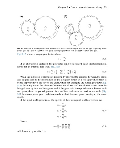
FIG. 3.1 Examples of the dependency of direction and velocity of the output shaft on the type of gearing. (A) A
simple gear train consisting of two spur gears. (B) Simple gear train, with the addition of an idler gear.
Fig. 3.1A shows a simple gear train, where,
N 2
n ¼ (3.2)
N 1
If an idler gear is included, the gear ratio can be calculated in an identical fashion,
hence for an external gear train, Fig. 3.1B,
u i N 2 N 3 N 3
n ¼ ¼ ¼ (3.3)
u o N 1 N 2 N 1
While the inclusion of idler gears is useful by allowing the distance between the input
and output shaft to be determined by the designer, which in a two-gear wheel train is
solely dependent on the size of the gears, while not changing the overall gear ratio, Eq.
(3.2). In many cases the distance between the driver and the driven shafts must be
bridged over by intermediate gears, and if the gear ratio is required cannot be met with
two gears, then compound gears on intermediate shafts can be used, as shown in (Fig.
3.2). In a compound gear, each intermediate shaft has two gears, rotating at the same
speed.
If the input shaft speed is u 1 , the speeds of the subsequent shafts are given by;
N 1
u A ¼ u i
N 2
N 3
u B ¼ u A (3.4)
N 4
N 5
u o ¼ u B
N 6
Hence,
u o N 2 N 4 N 6
n ¼ ¼ (3.5)
u i N 1 N 3 N 5
which can be generalised to,