
Page 87 - Electric Drives and Electromechanical Systems
P. 87
80 Electric Drives and Electromechanical Systems
This example demonstrates that the output speed can be modified by changing the angular
velocity of the ring, and that the direction of the ring adds or subtracts angular velocity to the
output.
nnn
3.1.3 Harmonic gearbox
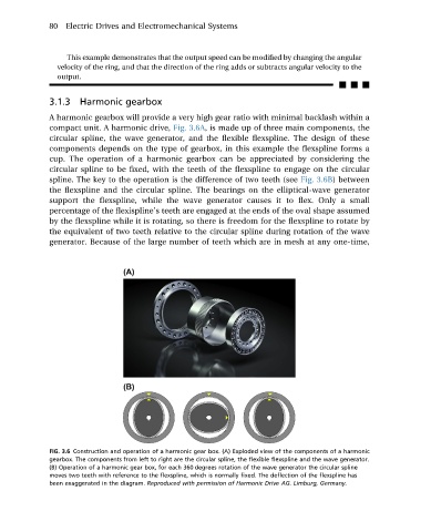
A harmonic gearbox will provide a very high gear ratio with minimal backlash within a
compact unit. A harmonic drive, Fig. 3.6A, is made up of three main components, the
circular spline, the wave generator, and the flexible flexspline. The design of these
components depends on the type of gearbox, in this example the flexspline forms a
cup. The operation of a harmonic gearbox can be appreciated by considering the
circular spline to be fixed, with the teeth of the flexspline to engage on the circular
spline. The key to the operation is the difference of two teeth (see Fig. 3.6B)between
the flexspline and the circular spline. The bearings on the elliptical-wave generator
support the flexspline, while the wave generator causes it to flex. Only a small
percentage of the flexispline’s teeth are engaged at the ends of the oval shape assumed
by the flexspline while it is rotating, so there is freedom for the flexspline to rotate by
the equivalent of two teeth relative to the circular spline during rotation of the wave
generator. Because of the large number of teeth which are in mesh at any one-time,
FIG. 3.6 Construction and operation of a harmonic gear box. (A) Exploded view of the components of a harmonic
gearbox. The components from left to right are the circular spline, the flexible flexspline and the wave generator.
(B) Operation of a harmonic gear box, for each 360 degrees rotation of the wave generator the circular spline
moves two teeth with reference to the flexspline, which is normally fixed. The deflection of the flexspline has
been exaggerated in the diagram. Reproduced with permission of Harmonic Drive AG. Limburg, Germany.