
Page 91 - Electric Drives and Electromechanical Systems
P. 91
84 Electric Drives and Electromechanical Systems
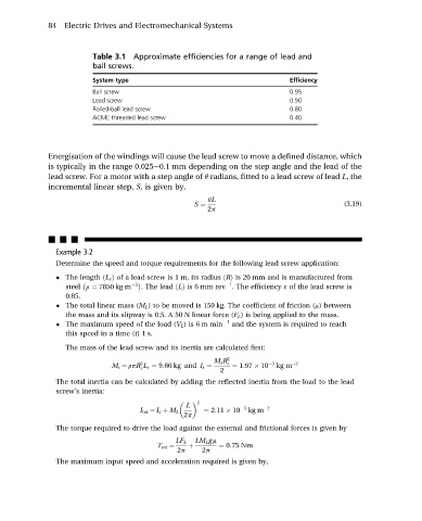
Table 3.1 Approximate efficiencies for a range of lead and
ball screws.
System type Efficiency
Ball screw 0.95
Lead screw 0.90
Rolled-ball lead screw 0.80
ACME threaded lead screw 0.40
Energisation of the windings will cause the lead screw to move a defined distance, which
is typically in the range 0.025e0.1 mm depending on the step angle and the lead of the
lead screw. For a motor with a step angle of q radians, fitted to a lead screw of lead L, the
incremental linear step, S, is given by,
qL
S ¼ (3.19)
2p
nnn
Example 3.2
Determine the speed and torque requirements for the following lead screw application:
The length ðL s Þ of a lead screw is 1 m, its radius ðRÞ is 20 mm and is manufactured from
3 1
steel r ¼ 7850 kg m . The lead ðLÞ is 6 mm rev . The efficiency ε of the lead screw is
0.85.
The total linear mass (M L ) to be moved is 150 kg. The coefficient of friction (m) between
the mass and its slipway is 0.5. A 50 N linear force (F L ) is being applied to the mass.
The maximum speed of the load (V L ) is 6 m min 1 and the system is required to reach
this speed in a time (t)1 s.
The mass of the lead screw and its inertia are calculated first:
M s R 2
2 s 3 2
M s ¼ rpR L s ¼ 9:86 kg and I s ¼ ¼ 1:97 10 kg m
s
2
The total inertia can be calculated by adding the reflected inertia from the load to the lead
screw’s inertia:
2
L 3 2
I tot ¼ I s þ M L ¼ 2:11 10 kg m
2p
The torque required to drive the load against the external and frictional forces is given by
LF L LM L gm
T ext ¼ þ ¼ 0:75 Nm
2p 2p
The maximum input speed and acceleration required is given by,