Page 90 - Electric Drives and Electromechanical Systems
P. 90

Chapter 3   Power transmission and sizing 83


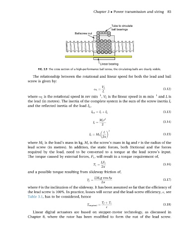
                      FIG. 3.9 The cross section of a high-performance ball screw, the circulating balls are clearly visible.
                   The relationship between the rotational and linear speed for both the lead and ball
                 screw is given by:
                                                          V L
                                                     u L ¼                                  (3.12)
                                                          L
                                                         1
                 where u L is the rotational speed in rev min , V L is the linear speed in m min  1  and L is
                 the lead (in metres). The inertia of the complete system is the sum of the screw inertia I s
                 and the reflected inertia of the load I L ,
                                                                                            (3.13)
                                                    I tot ¼ I s þ I L
                                                         M s r  2
                                                     I s ¼                                  (3.14)
                                                          2
                                                              2

                                                           L
                                                   I L ¼ M L                                (3.15)
                                                          2p
                 where M L is the load’s mass in kg, M s is the screw’s mass in kg and r is the radius of the
                 lead screw (in metres). In addition, the static forces, both frictional and the forces
                 required by the load, need to be converted to a torque at the lead screw’s input.
                 The torque caused by external forces, F L , will result in a torque requirement of,
                                                         LF L
                                                     T L ¼                                  (3.16)
                                                          2p
                 and a possible torque resulting from slideway friction of,
                                                      LM L g cos qm
                                                  T f ¼                                     (3.17)
                                                          2p
                 where q is the inclination of the slideway. It has been assumed so far that the efficiency of
                 the lead screw is 100%. In practice, losses will occur and the lead-screw efficiency, ε; see
                 Table 3.1, has to be considered, hence
                                                          T f þ T L
                                                  T required ¼                              (3.18)
                                                            ε
                   Linear digital actuators are based on stepper-motor technology, as discussed in
                 Chapter 8, where the rotor has been modified to form the nut of the lead screw.
   85   86   87   88   89   90   91   92   93   94   95