
Page 94 - Electric Drives and Electromechanical Systems
P. 94
Chapter 3 Power transmission and sizing 87
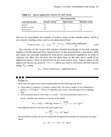
Table 3.2 Typical application factors for belt drives.
Drive characteristic
Load characteristics Smooth running Slight shocks Moderate shocks
Smooth 1.0 1.1 1.3
Moderate shocks 1.4 1.5 1.7
Heavy shocks 1.8 1.9 2.0
that can be transmitted; the number of teeth in mesh on the smaller pulley, which is
the system’s limiting value, and can be determined from,
Teeth on the small pulley
Teeth in mesh ¼ p 2 sin 1 ðD in D out Þ (3.28)
C 2p
The selection of the correct belt requires detailed knowledge of the belt material,
together with the load and drive characteristics. In the manufacturer’s data sheets, belts
and chains are normally classified by their power-transmission capabilities. In order to
calculate the effect that the load and the drive have on the belt, use is made of an
application factor, which is determined by the load and/or drive. Typical values of the
application factors are given in Table 3.2, which are used to determine the belt’s power
rating, P belt , using,
P belt ¼ Power requirement þ application factor (3.29)
nnn
Example 3.3
Determine the speed and torque requirements for the following belt drive:
A belt drive is required to position a 100 g load. The drive consists of two aluminium
3
pullies r ¼ 2770 kg m , 50 mm in diameter and 12 mm thick driving a belt weighting
20 g.
The maximum speed of the load is 2 m min 1 and the acceleration time is 0.1 s.
Firstly, calculate the moment of inertia of the pulley
M p R 2
2 p 5 2
M p ¼ rpR t p ¼ 0:065 kg; hence I p ¼ ¼ 2 10 kg m
p
2
The reflected inertia of the belt and load is given by,
MD 2 5 2
I L ¼ ¼ 7:5 10 kg m
4
The total driven inertia can now be calculated, noting that both pullies are moving at the same
speed.
I tot ¼ 2I p þ I L ¼ 1:15 10 4 kg m 2