
Page 89 - Electric Drives and Electromechanical Systems
P. 89
82 Electric Drives and Electromechanical Systems
As the eccentric rotates, it rolls the cycloid disc around the inner circumference of
the ring gear housing. The resultant action is similar to that of a disc rolling around the
inside of a ring. As the cycloid disc travels clockwise around the gear ring, the disc turns
counter clockwise on its axis. The teeth of the cycloid discs engage successively
with the pins on the fixed gear ring, thus providing the reduction in angular velocity.
The cycloid disc drives the low speed output shaft. The reduction ratio is determined
by the number of ‘teeth’ or lobes on the cycloid disc, which has one less ‘tooth’ than
there are rollers on the gear ring. The number of teeth on the cycloid disc equals the
reduction ratio, as one revolution of the high-speed shaft, causes the cycloid disc to
move in the opposite direction by one lobe.
3.2 Lead and ball screws
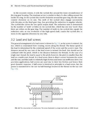
The general arrangement of a lead screw is shown in Fig. 3.8,asthe screwisrotated, the
nut, which is constrained from rotating, moves along the thread. The linear speed of
the load is determined by the rotational speed of the screw and the screw’s lead. The
distance moved by one turn of the lead screw is termed the lead: this should not be
confused with the pitch, which is the distance between the threads. In the case of a
single start thread, the lead is equal to the pitch; however, the pitch is smaller than the
lead on a multi-start thread. In a lead screw there is direct contact between the screw
and the nut, and this leads to relatively high friction and hence an inefficient drive. For
precision applications, ball screws are used due to their low friction and hence their
good dynamic response. A ball screw is identical in principle to a lead screw, but the
power is transmitted to the nut via ball bearings located in the thread on the nut (see
Fig. 3.9).
FIG. 3.8 The cross section of a lead screw. The screw illustrated is a single start with an ACME thread.