
Page 84 - Electric Drives and Electromechanical Systems
P. 84
Chapter 3 Power transmission and sizing 77
motion of the gear’s bearing. Helical gears (see Fig. 3.3B) are widely used in robotic
systems since they give a higher contact ratio than spur gears for the same size; the
penalty is an axial gear load. The limiting factors in gear transmission are the stiffness of
the gear teeth, which can be maximised by selecting the largest-diameter gear wheel
which is practical for the application, and backlash or lost motion between individual
gears. The net result of these problems is a loss in accuracy through the gear train, which
can have an adverse effect on the overall accuracy of a controlled axis.
In the gear trains so far discussed, the input shaft is parallel to the output shaft, if a
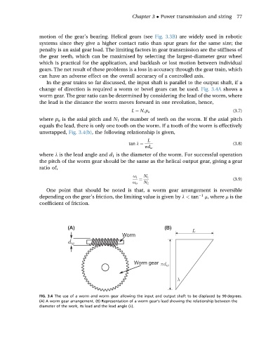
change of direction is required a worm or bevel gears can be used. Fig. 3.4A shows a
worm gear. The gear ratio can be determined by considering the lead of the worm, where
the lead is the distance the worm moves forward in one revolution, hence,
L ¼ N 1 p a (3.7)
where p a is the axial pitch and N 1 the number of teeth on the worm. If the axial pitch
equals the lead, there is only one tooth on the worm. If a tooth of the worm is effectively
unwrapped, Fig. 3.4(b), the following relationship is given,
L
tan l ¼ (3.8)
pd w
where l is the lead angle and d 1 is the diameter of the worm. For successful operation
the pitch of the worm gear should be the same as the helical output gear, giving a gear
ratio of,
u i N 1
¼ (3.9)
u o N 2
One point that should be noted is that, a worm gear arrangement is reversible
depending on the gear’s friction, the limiting value is given by l < tan 1 m, where m is the
coefficient of friction.
(A) (B)
FIG. 3.4 The use of a worm and worm gear allowing the input and output shaft to be displaced by 90 degrees.
(A) A worm gear arrangement. (B) Representation of a worm gear’s lead showing the relationship between the
diameter of the work, its lead and the lead angle (l).