
Page 85 - Electric Drives and Electromechanical Systems
P. 85
78 Electric Drives and Electromechanical Systems
In any gear train clearance is provided between the mating gear teeth, to ensure that
the gears mesh without binding and to provide space for a film of lubricating oil between
the teeth. However, this clearance will cause lost motion between the input and output
of the gear train, resulting in positional errors. To eliminate backlash several approaches
can be employed;
Specially manufactured precision gear trains that minimise error and bearing play.
Other types of gearboxes can be used, for example the harmonic gearboxes have
backlash in the order of arc-minutes depending on the power transmission
requirement. An alternative is the cycloid gearbox which has no teeth, just rolling
surfaces, giving zero backlash.
The design of the gear can be modified to reduce backlash. A commonly used
method is to use Split gearing, where the gearwheel is effectively split into two.
One-half is fixed to a shaft while the other half is displaced by a tooth, the spring
results in the lost motion being significantly reduced, providing the load limitations
are not exceeded. This approach is shown in Fig. 4.15, when two resolvers are
connected to increase the resolution of a measurement system.
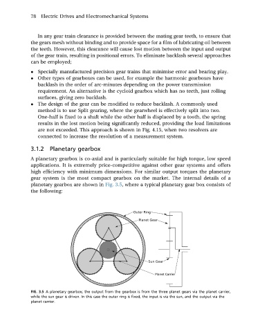
3.1.2 Planetary gearbox
A planetary gearbox is co-axial and is particularly suitable for high torque, low speed
applications. It is extremely price-competitive against other gear systems and offers
high efficiency with minimum dimensions. For similar output torques the planetary
gear system is the most compact gearbox on the market. The internal details of a
planetary gearbox are shown in Fig. 3.5, where a typical planetary gear box consists of
the following:
FIG. 3.5 A planetary gearbox; the output from the gearbox is from the three planet gears via the planet carrier,
while the sun gear is driven. In this case the outer ring is fixed, the input is via the sun, and the output via the
planet carrier.