
Page 77 - Electric Machinery Fundamentals
P. 77
IN'rROOUCTION TO MACH INERY PRINCIPLES 53
+
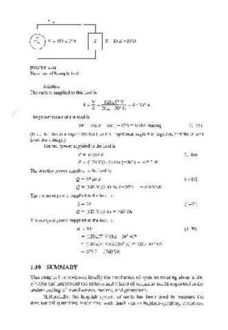
'\... V=1 20 L Ooy z z ~ 20 L -30'[1
l 1GURE \ -34
'
The circuit of Example I-I I.
SolutiOIl
The current supplied to this load is
I = Y = l20L O V 6L30' A
'
Z 20L - 30' n
(
The power factor of the load is
PF ~ cos 8 = cos (- 30' ) = 0.866 leading (1 - 71)
(Note that this is a capacitive load, so the impedance angle () is negative, and the current
leads the voltage.)
The real power supplied to the load is
P = VI cos () (1-60)
P = (1 20 V)(6 A) cos (-30' ) = 623.5 W
The reactive power supplied to the load is
Q = VI sin 8 (1- 61)
Q = (120 V)(6A) sin (-30') = - 360 VAR
The apparent power supplied to the load is
S = VI (1-62)
Q = (1 20 V)(6 A) = 720 VA
The complex power supplied to the load is
S = VI* (1-70)
= (120LO' V)(6L-30' A)*
= (120LO' V)(6 L30' A) = n0L30' VA
= 623.5 - j360 VA
1.10 SUMMARY
This chapter has reviewed briefly the mechanics of systems rotating about a sin-
gle axis and introduced the sources and effects of magnetic fields important in the
understanding of transformers, motors, and generators.
Historically, the English system of units has been used to measure the
mechanical quantities associated with machines in English-speaking countries.