
Page 76 - Electric Machinery Fundamentals
P. 76
52 ELECTRIC MACHINERY FUNDAMENTALS
p
Q +
v z z~ 121 Lon
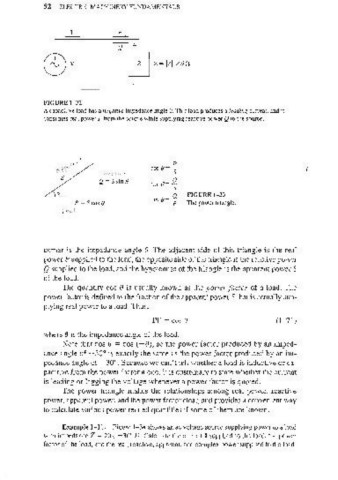
FIGURE 1-32
A capacitive load has a negative impedance angle B. This load produces a le(l(/illg current, and it
consumes real power P from the source while supplying reactive power Q to the source.
p
COSB= S (
( C".( -I ,(,. ~
Q = S sin e sin 8= ~
tan 8 = ~ FIGURE 1- 33
P = SeasB The power triangle.
(<>c.\
corner is the impedance angle 8. The adjacent side of this triangle is the real
power P supplied to the load, the opposite side of the triangle is the reactive power
Q supplied to the load, and the hypotenuse of the triangle is the apparent power S
of the load.
The quantity cos e is usually known as the power Jactor of a load. The
power factor is defined as the fraction of the apparent power S that is actually sup-
plying real power to a load. Thus,
PF = cos 8 (l-7l)
where 8 is the impedance angle of the load.
Note that cos 0 = cos (- 0), so the power factor produced by an imped-
ance angle of + 30° is exactly the same as the power factor produced by an im-
pedance angle of - 30°. Because we can't ten whether a load is inductive or ca-
pacitive from the power factor alone, it is customary (Q state whether the current
is leading or Jagging the voltage whenever a power factor is quoted.
The power triangle makes the relationships among real power, reactive
power, apparent power. and the power factor clear, and provides a convenient way
to calculate various power-related quantities if some of them are known.
Example 1- 11. Figure 1-34 shows an ac voltage source supplying power to a load
with impedance Z = 20L - 30 D. Calculate the current I supplied to the load, the power
0
factor of the load, and the real, reactive, apparent, and complex power supplied to the load.